Ga door naar hoofdinhoud

Released circa 2011.

1 Vragen Bekijk alle

Why is the back-light not turning on

Block Image

Laptop turns on but screen not displaying due to back-light off

Block Image
Block Image
Block Image
Block Image

These are the images of my motherboard

New image

Block Image
Block Image

These are two new images , help me identify the areas I have to measure

Block Image
Block Image
Beantwoord! Bekijk het antwoord Dit probleem heb ik ook

Is dit een goede vraag?

Score 1
2 opmerkingen

[image|3435557]

[image|3435556]

[image|3435554]

[image|3435555]

door

I checked the pins and their voltages are as follows

Pin 40 = 19.83

Pin 38 = 19.83

Pin 39 = 19.83

Pin 36 = 0.03

Pin 35 = 0.39


The yellow area seems fine there seems to be a hole made there during  manufacturing, and it's found directly under the tag where the screen cable fits.


Thanks

door

Voeg een opmerking toe

4 Antwoorden

Gekozen oplossing

@lloydkwakye first you need to determine if it is the backlight that is not working. Try this. turn the computer on. Next, use a flashlight and shine the beam at an angle against the screen. Do that in a darkened room. See if you can make out shadows or shapes. If you do, then it is your backlight that has failed.

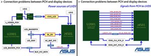
Next, connect an external monitor and make sure that this monitor displays everything properly. Now you have it narrowed down. From here on you will have to open your computer up. Next you check the display adapter. You need to check the voltages for your backlight on this connector. It could be as simple as a blown fuse, to as complex as a failed WLED driver etc.

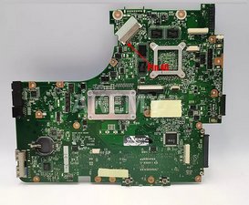
To help you further, we would need the exact model of your motherboard and we would need to see your motherboard. That way we can check for components that may have failed etc.

Post some good pictures of your motherboard with your Question. Adding images to an existing question - iFixit Repair Guide

Update 10/01/2024

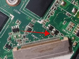
@lloydkwakye thank you for the images. We need to get one more. This one closer to the connector for your display. It'll be marked as J4501. You can check your voltages on that one.

Block Image

Pin 40, 39 and 38 are the positive voltages for your LED's. Let us know what voltages your multimeter measures. Remember that those contacts are small. Use a magnifying sources and some needle tips for your meter. You don't want to shorten out those pins.

Pin 36 is Backlight enable and pin 35 is your LCD backlight power modulator (brightness of the backlight) again we need to voltages on that. You do need to make all measurements with the computer turned on. Again, do not shorten out the contacts with your probes.

Update 10/24/2024

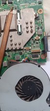
@lloydkwakye we need you to measure the voltage on Pin 38, 39, and 40 to see what voltage you get. I've marke d pin 40 on the previous image. 39 and 38 are just adjacent to it. The expectation here is somewhere between 30 and 40VDC. If you only get the same voltage as your system voltage you know the boost circuit is the issue. For that you need to check the components which are located on the other side but are covered by the fan cable.

Block Image

If the voltage is to high then the issue are the LED backlights and if the voltage is 0 then the issue is the power circuit having failed. Let us know what you find out.

Update 10/27/2024

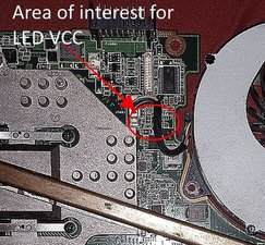
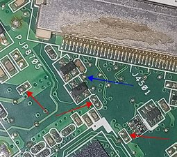
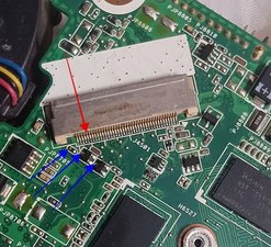
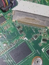
@lloydkwakye nothing is ever easy is it. Amazingly enough the components that are in the schematic part of the LED-VCC circuit seem to have never been populated on your board. We may just have a different revision here. I did notice an oddity. Check the hole (yellow arrow) and see if that is normal for the board or if something has happened on the other side. Have you have a chance of measuring the voltage on your display connector yet.

Block Image

Update 01/16/2025

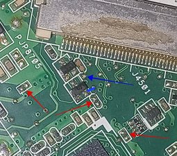
@lloydkwakye this looks wrong. There is a possibility that you have a lost component and bad solder pads. The area that looks odd (red arrow) should have an inductor for the BK_EN circuit. Post a clear picture of that area. If it is missing, then your backlight will not turn on since it does not get the enable signal.

Block Image

Update 01/18/2025

@lloydkwakye

Block Image

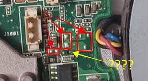
if this would have been a non-populated part then I would expect it to look like the rest of those areas (red arrows). I would measure the voltage on the solder pad (blue arrow) and see if there is any voltage that corresponds to what BK_EN needs. IF it does then apply a jumper from the point the BK_EN on the display adapter.

Update 01/21/2025

@lloydkwakye

Block Image

now measure these voltages. If those are okay,we can simply run a jumper from the resistor to pin 36. Do not do this without checking the voltage first.

Was dit antwoord nuttig?

Score 2

12 opmerkingen:

I could see images on the screen when I used the flashlight.

I add images of my motherboard very soon.

door

I have uploaded the image you requested

door

@lloydkwakye alright. Thank you and let me see if we can figure it out. Your images are a bit fuzzy which looks worse when we have to zoom in :-)

door

I will try and snap another one

door

@oldturkey03 I have uploaded new images.

door

7 commentaren meer tonen

Voeg een opmerking toe

Hi @lloydkwakye

To make it easier to do, if there's a display shown on an external monitor (TV?) connected to the laptop's HDMI port (press Fn + F8 both together to switch display output from laptop to external) then if you have Windows installed in the laptop go to the Power options and change the Lid switch setting to do nothing then select Apply.

Restart the laptop in the normal manner and check if the laptop screen turns on.

If it does there may be a problem with the lid switch in the laptop. The switch sends a signal to the I/O chip showing whether the lid is open or closed. When it is closed the I/O chip either applies or removes (not sure which) a voltage signal on the backlight enable (BL_EN) lead to the display.

There's always power being supplied to the LCD panel backlights circuit from the motherboard (in your case you have proven this) but it is the voltage signal status on the BL_EN lead that tells the LCD panel whether to turn the backlights on or off.

The backlight power on the motherboard is not turned off when the screen goes dark. It's turned off in the LCD panel

Here's an image from the service manual showing in block form the power supplies to the screen.

Unfortunately without knowing the make and model number of the LCD panel so that its datasheet can be found (I can't find it anyway) I don't know which pin on the LVDS connector on the motherboard the BL_EN lead is, so that you can check.

If changing the Lid switch power setting makes no difference it still could be that there's a problem on the BL_EN lead or it is in the display panel.

Block Image

(click on image)

Was dit antwoord nuttig?

Score 1

1 Opmerking:

@jayeff I will give it a try

door

Voeg een opmerking toe

@oldturkey03, will this image be OK.

Please let me know from your judgement if a component is supposed to be there.

If yes how to I make amendments for it.

Thank you

Block Image
Block Image

Was dit antwoord nuttig?

Score 0
Voeg een opmerking toe

@oldturkey03 when I measured the area with the blue arrow the voltage was 0.04, however the part marked with the blue ink read 3.37

Block Image

Please kindly direct me to the part called BK_EN

Was dit antwoord nuttig?

Score 0

1 Opmerking:

Hi @lloydkwakye

@oldturkey03 told you 4 days ago in a comment in the Chosen Solution which pin on the LVDS connector is the BK_EN lead.

Use an Ohmmeter to prove continuity between the blue arrow point on the motherboard and pin #36

If the point with the blue arrow connects to this pin, then if you solder a wire between the blue arrow point and the blue ink point hopefully the backlight will turn on when the laptop is turned on.

Do the Ohmmeter measurement and the soldering on the wire etc with the battery disconnected from the motherboard and also the charger as well so as to not cause any more damage to the motherboard.

Reconnect them when you have finished the work.

Just curious as to the history of the motherboard because there should be an inductor connected between those two points and not as it appears now with nothing there. It is very unusual that it is missing as it looks like its removal wasn't an accident but deliberately done

door

Voeg een opmerking toe

Voeg je antwoord toe

Lloyd Kwakye zal eeuwig dankbaar zijn.
Weergavestatistieken:

Afgelopen 24 uren: 0

Afgelopen 7 dagen: 8

Afgelopen 30 dagen: 16

Altijd: 159