Inleiding
Follow this guide to replace the screen and battery assembly on your Samsung Galaxy S22+.
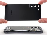
This guide is written for the screen and battery assembly. The assembly consists of the screen, battery, and frame together in one part. Be sure you have the right part before you begin the repair.
Note: Retaining water resistance after the repair will depend on how well you reapply the adhesive, but your device will lose its IP (Ingress Protection) rating.
Wat je nodig hebt
-
-
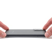
Insert a SIM eject tool, bit, or straightened paper clip into the SIM card tray hole on the bottom edge of the phone.
-
Press the SIM eject tool into the SIM card tray hole to eject the SIM card tray.
-
Remove the SIM card tray.
-
-
-
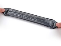
Prepare an iOpener and apply it to the bottom edge of the back cover for three minutes to loosen the adhesive underneath.
-
-
-
Secure a suction handle to the bottom edge of the back cover, as close to the edge as possible.
-
Lift the back cover with the suction handle to create a small gap between the back cover and the frame.
-
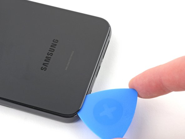
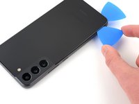
Insert an opening pick into the gap you created.
-
-
-
Remove the suction handle.
-
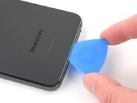
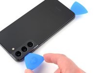
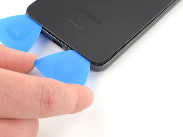
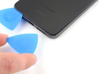
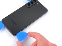
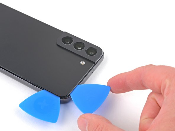
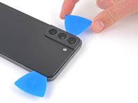
Slide the opening pick along the bottom edge to slice the adhesive.
-
Leave the opening pick inserted near the bottom left corner to prevent the adhesive from resealing.
-
-
-
Apply the heated iOpener to the left edge of the phone for 3 minutes to soften the adhesive.
-
Reheat your iOpener for 30 seconds if necessary.
-
-
-
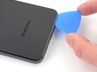
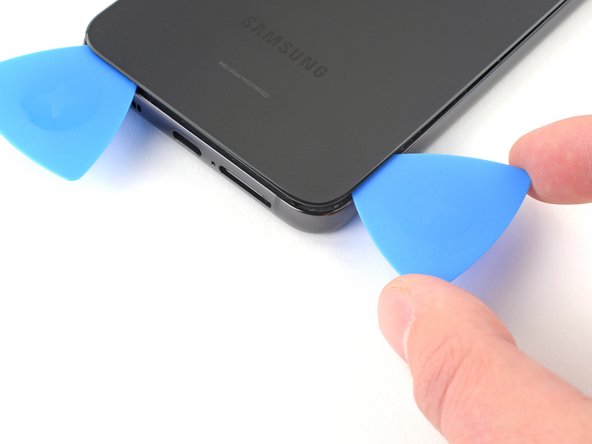
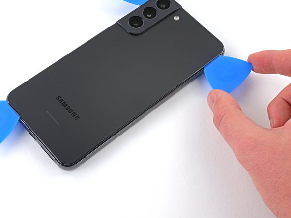
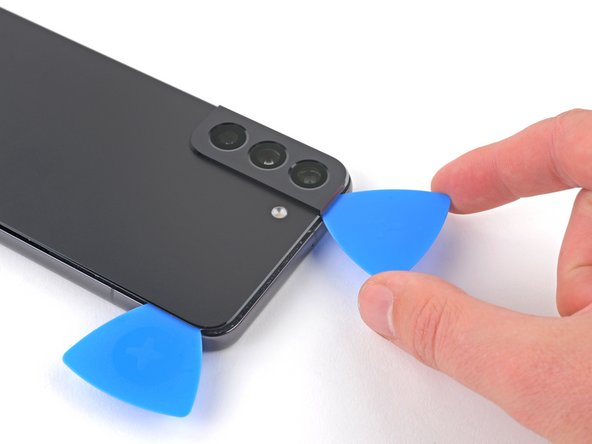
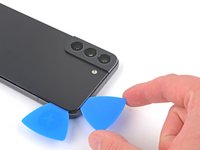
Insert a second opening pick into the gap created near the bottom left corner.
-
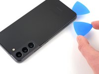
Slide the opening pick along the left edge to slice the adhesive.
-
Leave the opening pick inserted near the top left corner to prevent the adhesive from resealing.
-
-
Gereedschap gebruikt in deze stap:Tweezers$4.99
-
Remove the back cover.
-
This is a good point to power on your phone and test all functions before sealing it up. Be sure to power your phone back down completely before you continue working.
-
Remove any adhesive chunks with a pair of tweezers or your fingers. Apply heat if you're having trouble separating the adhesive.
-
If you're using custom-cut adhesives, follow this guide.
-
If you're using double-sided tape, follow this guide.
-
-
-
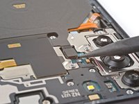
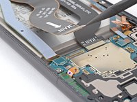
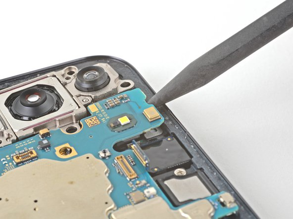
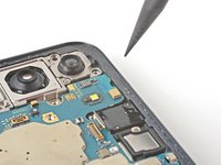
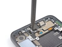
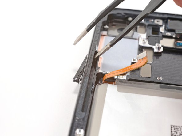
Use the pointed end of your spudger to pry up and disconnect the charging coil's press connector from the motherboard.
-
-
-
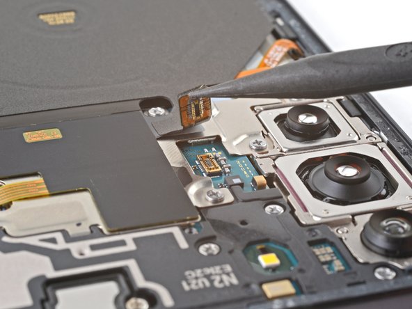
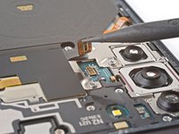
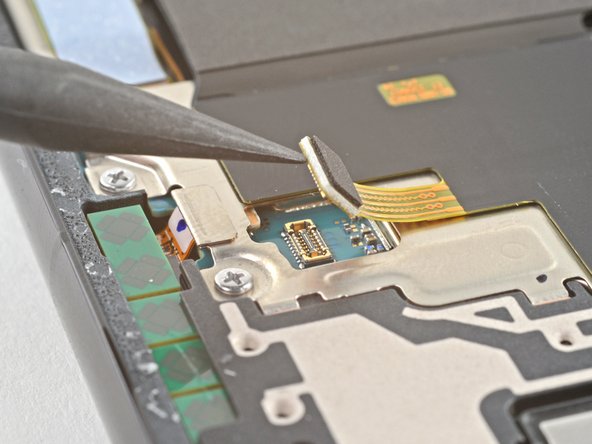
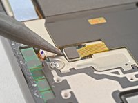
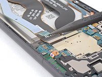
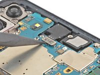
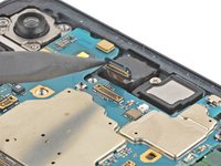
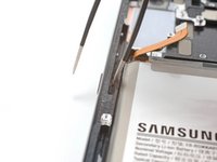
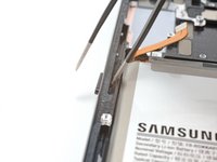
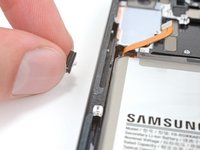
Use the pointed end of your spudger to pry up and disconnect the NFC antenna cable from the motherboard.
-
-
-
Use your Phillips screwdriver to remove the six 3.5 mm screws securing the charging coil.
-
-
-
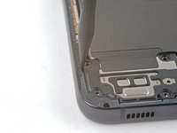
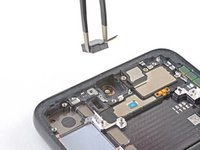
Use your Phillips screwdriver to remove the seven 3.5 mm screws securing the loudspeaker.
-
-
-
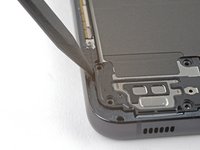
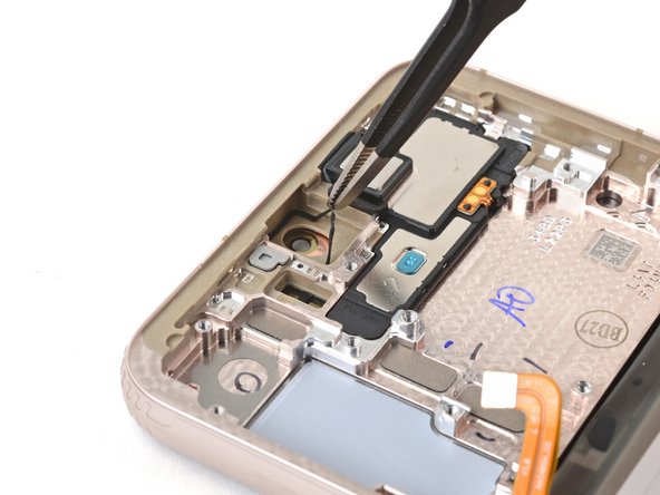
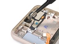
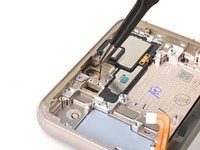
Insert your spudger in between the left edge of the loudspeaker and the frame.
-
Pry up to disconnect the clips securing the loudspeaker.
-
-
-
-
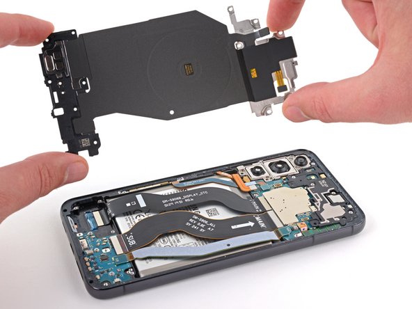
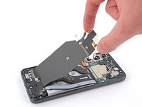
Gently remove the charging coil & NFC antenna assembly.
-
-
-
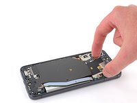
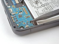
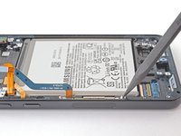
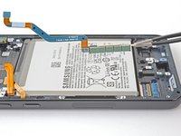
Use your spudger to pry up and disconnect the battery's press connector.
-
-
-
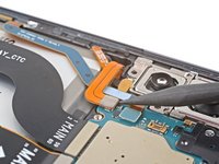
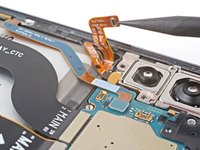
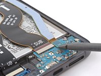
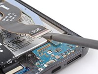
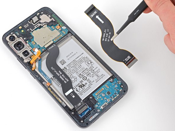
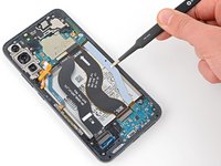
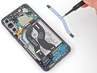
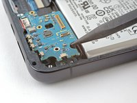
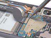
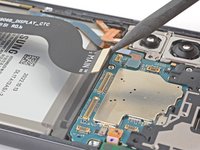
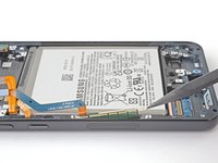
Use your spudger to pry up and disconnect the primary interconnect cable from the motherboard.
-
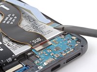
Use your spudger to pry up and disconnect the secondary interconnect cable from the motherboard.
-
-
-
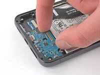
Use your Phillips screwdriver to remove the three 3.4 mm screws securing the charging board.
-
-
-
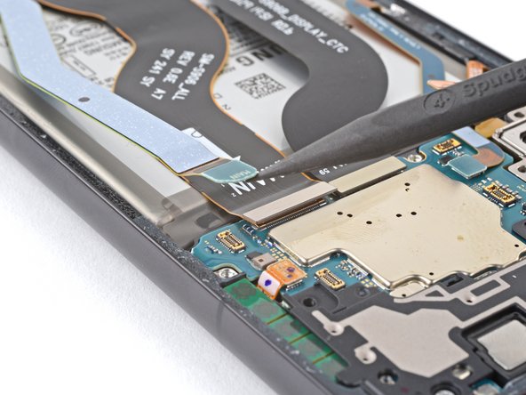
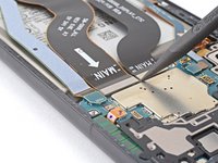
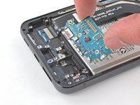
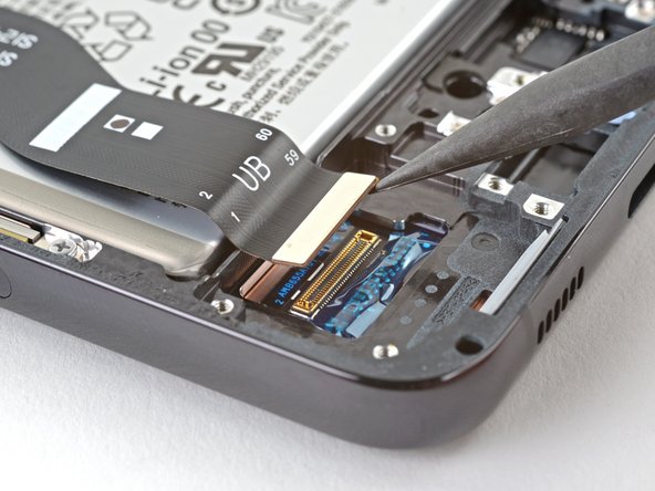
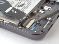
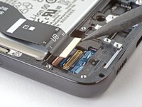
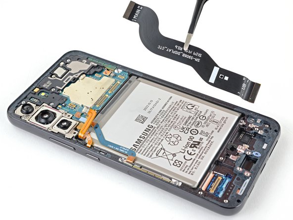
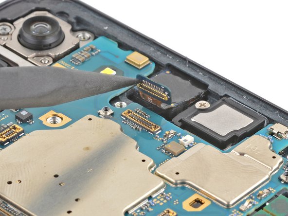
Use your spudger to pry up and disconnect the display cable from the motherboard.
-
-
-
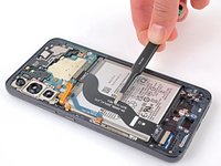
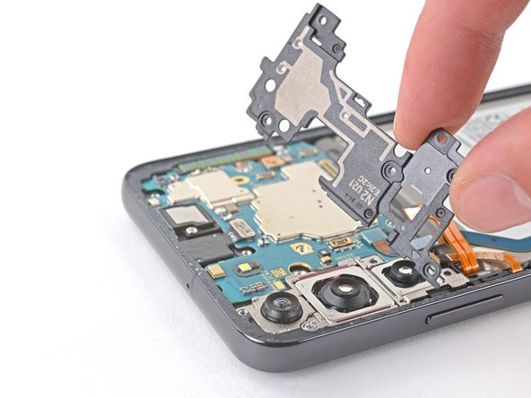
Use your Phillips screwdriver to remove the four 3.5 mm screws securing the motherboard cover.
-
-
-
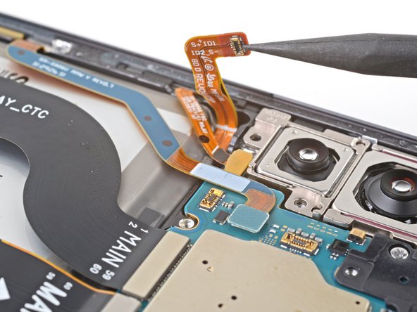
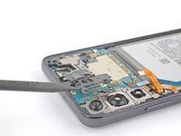
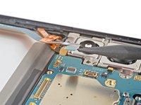
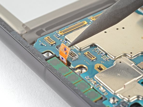
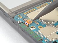
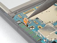
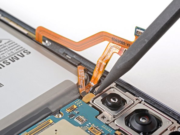
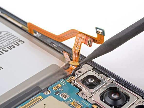
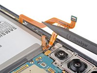
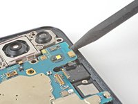
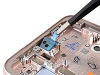
Use your spudger to pry up and disconnect the left mmWave antenna from the motherboard.
-
-
-
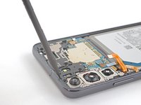
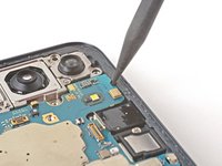
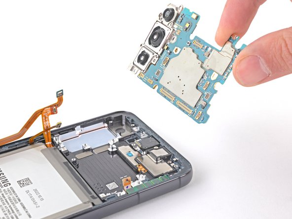
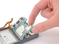
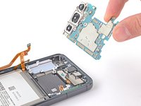
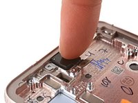
Use your Phillips screwdriver to remove the 3.5 mm screw securing the camera module and motherboard to the frame.
-
-
-
Prepare an iOpener and apply it to the front camera for three minutes.
-
Place the iOpener on your work surface and lay the top edge of the screen on it to heat the camera from underneath.
-
-
-
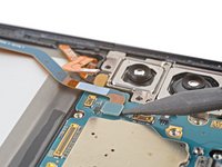
Remove the black adhesive liner from the front-facing camera recess.
-
Peel and remove the foam liner from the new frame.
-
-
-
Remove the clear liner from the front-facing camera adhesive.
-
Place the adhesive in the camera recess with its pull tab facing right.
-
Remove the blue adhesive liner using its pull tab.
-
Insert the front-facing camera into its recess in the frame and apply pressure to secure it.
-
-
-
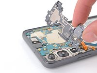
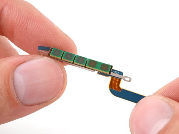
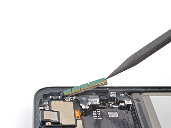
Use your Phillips screwdriver to remove the two 3.5 mm screws securing the left 5G mmWave antenna.
-
-
-
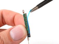
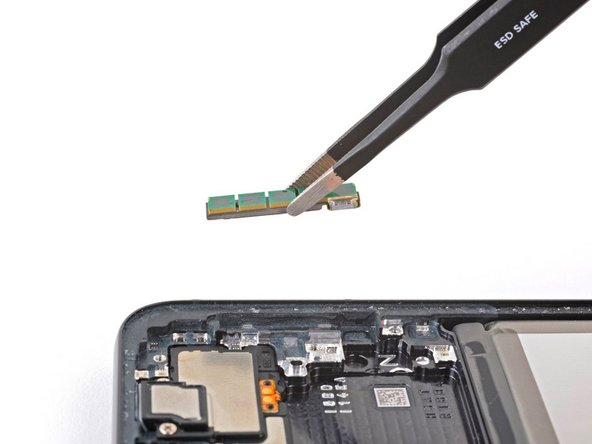
Remove the antenna and connector from the old bracket.
-
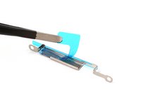
Remove the L-shaped adhesive liner from your new bracket.
-
Place the antenna in the bracket's recess with the connector fed underneath the longer screw mount.
-
Remove the thin adhesive liner on the outside of the bracket before installing it in the frame.
-
-
-
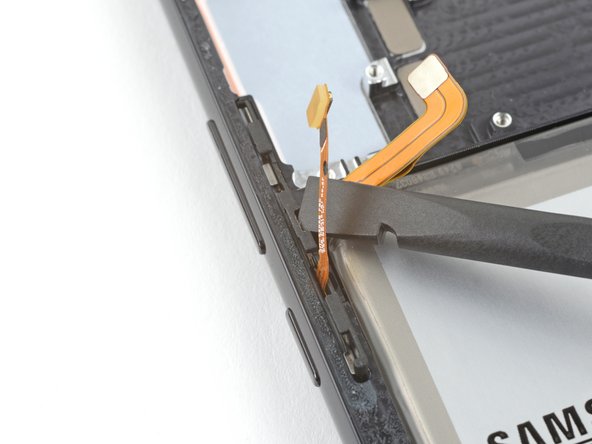
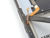
Insert the corner of your spudger in the tab on the side button bracket.
-
Twist the spudger upward to pry and loosen the side button bracket from its recess in the frame.
-
-
-
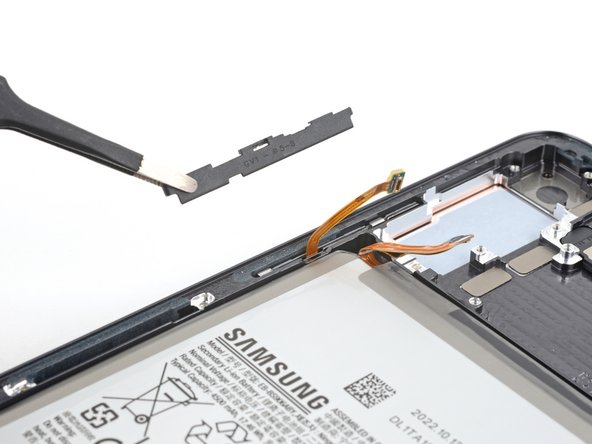
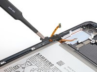
Use blunt nose tweezers or your fingers to grab and remove the side button bracket.
-
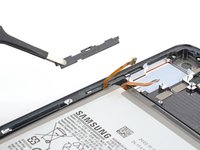
Use your fingers to grab and remove the button pad.
-
-
-
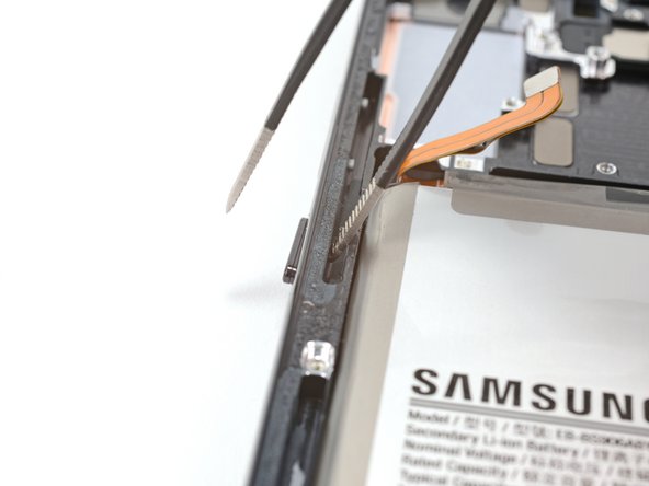
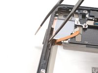
Insert one arm of your blunt nose tweezers into the side button's recess.
-
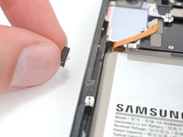
Push the power button's peg through the frame until you can grab the button with your fingers.
-
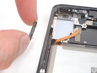
Use your fingers to grab and remove the power button.
-
-
-
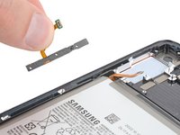
Insert one arm of your blunt nose tweezers into the side button's recess.
-
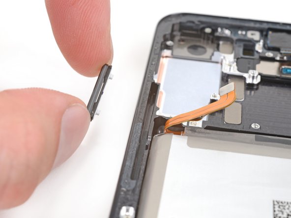
Push both pegs of the volume buttons through the frame until you can grab the buttons with your fingers.
-
Use your fingers to grab and remove the volume buttons.
-
-
-
Only the screen and battery assembly remains.
-


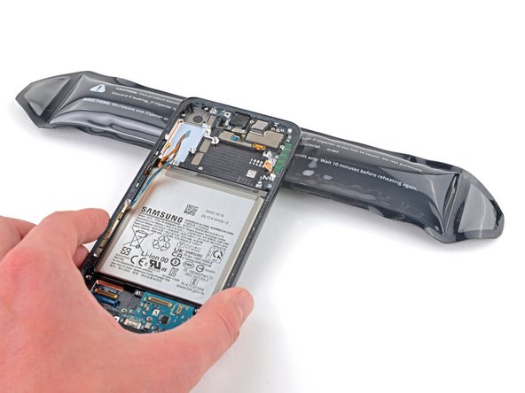


To reassemble your device, follow these instructions in reverse order.
Take your e-waste to an R2 or e-Stewards certified recycler.
Repair didn’t go as planned? Try some basic troubleshooting, or ask our Answers community for help.
To reassemble your device, follow these instructions in reverse order.
Take your e-waste to an R2 or e-Stewards certified recycler.
Repair didn’t go as planned? Try some basic troubleshooting, or ask our Answers community for help.
Annuleren: ik heb deze handleiding niet afgemaakt.
10 andere personen hebben deze handleiding voltooid.

4 opmerkingen
Very VERY detailed step by step instructions, will be performing this procedure In the next few days and this guide will most definitely be the most important tool to have on hand! Thank you for taking the time to put this together so completely!!
The most thorough guide I've seen. Thank you for your effort!
Thank you for this nice tutorial.
Quick question : when you’ll replace the screen, will the finger lock work with the new screen or will it be disactivated like when you replace your main “home” button on iPhones ?
Useful guide. Thank you. I believe instructions for removing the top loudspeaker assembly are missing.