
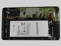
Nvidia Shield Tablet K1 Micro USB Port Replacement

Inleiding
Ga naar stap 1The Micro USB Port is for charging your tablet. If damage had ever occurred to it, you may find it loose, or not holding your charging cable.
Wat je nodig hebt


-
-
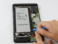
Starting at the Micro SD Card Slot and using the blue plastic opening tool, begin to maneuver the tool around the edges while applying light pressure to lift the panel upwards.
-
-
-
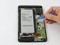
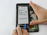
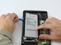
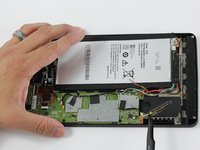
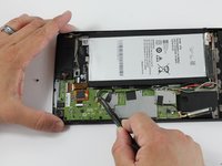
Using the blue plastic opening tool, place the lip of the tool underneath the battery as seen in the photo.
-
-
-
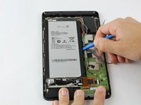
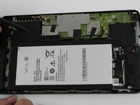
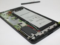
When the battery seems loose enough, use the blue plastic opening tool to lift the battery from the device.
The white wire is for temperature line. What about the green wire? I have generic battery almost same size ang xapacity but it had only 3 wires, red black ang white. Green is missing
-
-
-
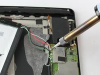
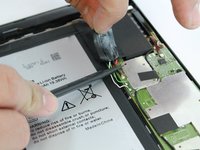
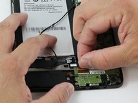
Using a soldering iron, desolder the four wires from the motherboard.
-
Once the wires are free from the motherboard, your battery should be free to remove from your device.
Where can I buy a replacement battery??
Where can I buy a replacement battery for my Nvidia tablet??
Aliexpress -[L508 3,8 V 3,7 V 5000 mAh [3565152] PLIB; polímero de iones de litio/Li-ion batería para tablet pc de autonomía, carga de dispositivos, corrección keystone automática, e-book; BL-T17 celular
Those replacement batteries only have 2 or 3 wires. Any ideas since the one on the Shield has 4 wires?
-
-
Gereedschap gebruikt in deze stap:Tweezers$3.99
-
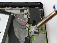
Use the angled tweezers to disconnect the black power cable from the mother board. The Cable should pop up from its slot when pulled.
You do not need to disconnect the antenna power cable. You only need to disconnect the other 2 black power cables. Just pull the antenna out together with the Mboard.
Did you not remove the battery and disoldered its cables? Why are they still in place?
-
-
-
-
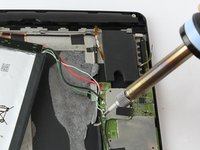
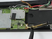
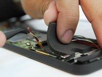
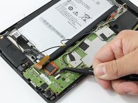
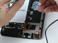
Using the angled tweezers, begin removing the antenna from the device.
You only need to free the antenna from the case. Leave it hanging from the Mboard.
-
-
-
While using the black plastic spudger tool, slowly lift the tape with your fingers and hold the wires down with the tool.
-
-
Gereedschap gebruikt in deze stap:Tweezers$4.99
-
Carefully remove the audio input films for each speaker from their respective ZIF (zero insertion force) connectors. These are the paper thin ribbons that have orange stripes along them.
-
Pull up the white latch on the ZIF connector, which will release the film and allow you to pull it out with tweezers.
-
Repeat this for both speakers.
How did you remove the antenna in step 10 without removing the audio input films? In this photo, the antenna is still in place. Your instructions are a complete mess!!!
-
-
-
Remove the power cables connecting the speakers to the battery. These are black wires with gold tips.
-
Again, use the tweezers to carefully pull them up from their places, they should pop right off.
Have you not already removed these in Step 7 ???
Removing cables already removed in step 7 ???
-
-
-
Free the speakers by removing their screws. You'll need the J000 Phillips-head screw Driver.
You only need to remove the speaker on the right of this photo, you can leave the other, longer one, in place.
Battery in place, cables soldered, antenna in place, etc, as if you haven’t done any of the previous 14 steps. What a mess…
I think what you meant was 3mm, not 30mm.
-
-
Gereedschap gebruikt in deze stap:Tweezers$4.99
-
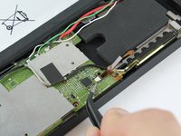
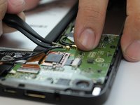
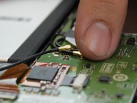
Using the tweezers or your fingers lift the remaining black wires from the motherboard.
-
-
-
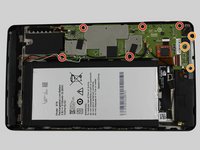
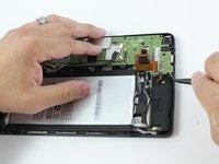
Remove the remaining screws holding the motherboard in place.
-
Screws description: 5 short black screw 20mm length and 30mm diameter.
-
Screws description: 3 long black screw 40 mm length and 20 mm diameter.
Mine had an additional screw on the top left corner of the motherboard. You can actually see it in this picture, directly above the left most screw.
I just realized that this is the screw described in step 8, which was supposed to be removed by this step. Guess I can't follow instructions.
-
-
-
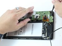
Using your tweezers, lightly lift around the edges to lift the motherboard.
-
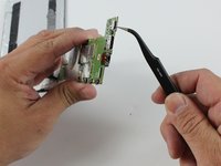
Before lifting the motherboard out, use your tweezers to disconnect rear camera's copper cable from the motherboard.
Congratulations, you’ve just ripped the connector for the front camera when you lifted the motherboard out. The other speaker needs to be removed BEFORE lifting the motherboard, and the front camera, which is glued in, loosened so it lifts out with the motherboard.
You can also lift the rear facing camera out. It’s held in only by some double sided tape. This will be necessary to plug it back in anyways.
I wish I had read the users’ comments before attempting this repair….
-
-
-
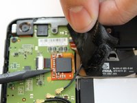
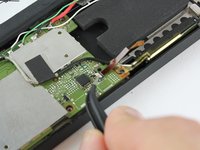
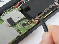
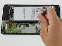
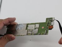
Use a soldering iron to desolder the Micro USB Port from the motherboard.
-
Now the Micro USB Port is free from the motherboard.
You will need to plug in both cameras first and install them together with the Mboard as the connectors are on the underside.
BIG NOTE: The entire bottom surface of the usb port is soldered down. You must first desolder the 5 contacts then heat the entire port until it comes loose.
How are we supposed to desolder the entire port with a soldering iron alone, as listed in the Tools Section ???? Also, even if I remove the USB port, do I not need a replacement one? Where is it in the list of required parts? The worst iFixIt guide ever !!!
There is no
Use a soldering iron to desolder the Micro USB Port from the motherboard.
Because the port is soldered at all four corners and the base and the connectors; the only way to do this is a heat gun built specifically for desoldering. Please, Ryan Butler, do not mislead people so that they ruin their mainboards.
To those reading this, buy a heat gun. If said heat gun costs more than a tablet from 2015, buy a new tablet and toss the old one. NVIDIA did not build this thing for home repair. This is disposable Android tech at its finest.
This component is in a minefield of other transistors and plastic components, so you must be careful. The connections and copper love to de-tin or delaminate.
Again, Ryan Butler's last step (step 20) is pure crap. Buy a heat gun.
To resolder the port, the contacts must have copper under them and solder on them or you're boned.
-


To reassemble your device, follow these instructions in reverse order.
To reassemble your device, follow these instructions in reverse order.
Annuleren: ik heb deze handleiding niet afgemaakt.
5 andere personen hebben deze handleiding voltooid.

Team

iFixit, Team 1-1, Weber Winter 2016 Lid van iFixit, Team 1-1, Weber Winter 2016
FIX-WEBER-W16S1G1
4 Leden
37 handleidingen geschreven
12 opmerkingen
Where I can find a micro UBS port for Nvidia shield tablet ?
Micro usb -B, Amazon.
it's a standard form factor, just check ebay
It might be cheaper to solder a new one. I would compare prices, and decide if the price is worth soldering. If you want experience in soldering, go the solder route. Refining this skill will help later if you need to solder anything else.
To remove the mainboard, it’s not necessary to remove the battery. I would strongly recommend to keep it in place.
De-soldering is sufficient.
Thanks for the tip, I’m about to change the port in mine.
This guide doesn’t mention what type of adhesives will work for reassembly?
How can I fix the USB port of my Nvidia Shield k1 any idea is better to replace a new port or solder .
Manque: Tresse à dessouder, soudure laiton (fils batterie + fixation Micro USB) + pâte a braser, fer à souder CMS (air chaud) (pour pin Micro USB)
Manque: Micro usb port neuf
Inutile: (3,4,5) juste dessouder les 4 fils, ne pas essayer de la décoller, ou utiliser un dissolvant si autre besoin de réparation.
Erreur : 7, le câble noir n'est pas un câble d'alimentation, pas besoin de le déconnecter, voir étape 8 et 14
Dernière étape, il reste le plus difficile, ressouder un port USB neuf sur la carte mère, facile, souder les 5 pins beaucoup moins et surtout quasi impossible avec un fer à souder standard, peut être avec l'aide d'un microscope ?
Il faut un poste soudure CMS et de la pate à braser que l'on aura déposer sur les pins avant de fixer le port usb sur la carte mêre.
Tuto Utile pour les propriétaires de tablette ayant le matériel et le savoir faire en électronique, inutile pour les autres, entre le savoir faire et le prix de l'investissement matériel. Cherchez un professionnel et compter 60-80 euros.
Thanks for the tips. I recommend using a de-soldering tool instead of braid though. It’s basically a spring loaded syringe that works backwards, sucking up the molten solder.
I see that the micro usb's weldings are immediately accessible, it is possible think to weld a wireless receiver?
beware the very small ribbon cable from the bottom speaker under the tape near to the micro USB port - I was very careful when peeling back the tape but I did not realise the last corner covered that ever so this piece connected at 90 degrees horizontally and it so easiy tore through. Now I have to figure out how to fix that as it appears to be glued into the speaker :( I know this is years later but any suggestions for that are appreciated - and I will look through the site for the same