Deze vertaling geeft mogelijk niet de meest recente updates van de bronhandleiding weer. Help ons met het updaten van de vertaling of bekijk de bronhandleiding.
Inleiding
Gebruik deze handleiding om de schermmodule van je Samsung Galaxy Note9 te vervangen.
Wat je nodig hebt
-
-
Druk aan de onderkant van de S-pen totdat je deze voelt en hoort klikken.
-
Laat de S-pen los zodat deze uit de telefoon komt.
-
Verwijder de S-pen.
-
-
-
Steek een uitwerptool in de kleine opening in de SIM-kaarthouder.
-
Druk op de tool om de SIM-kaarthouder uit te werpen.
-
-
-
Schakel je telefoon uit voordat je begint met het demonteren.
-
Gebruik een föhn, warmtepistool of prepareer een iOpener en leg deze direct op de rechterzijde van de achterkant van de telefoon gedurende een minuut. Hierdoor wordt de lijm eronder verzacht.
If using an iOpener it will need to be fully heated and set on for at least 5 minutes. You’ll know the phone is hot enough when its almost too hot to touch.
Just came here to say exactly that. The instructions should be amended to state that: "Get it fully hot and leave it there for at least three minutes solid."
-
-
-
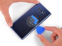
Druk een zuignap op de achterste behuizing.
-
Til de zuignap op om zo een opening te creëren tussen de achterste behuizing en het frame van de telefoon.
-
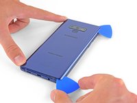
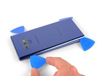
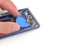
Steek een openingsplectrum in de opening.
It takes so much heat that it is concerning that damage might be caused to the internal parts. It is difficult to heat the glue, pull the case apart and insert the pick at same time. May need some more pointers to handle these situations first, to prevent possible damage. Also what about the glue that is heated and then cooled before opening? Does it run inside and cause greater adhesion after it cools? Another thing, the handling may cause the phone to turn back on while working to separate. Don't know that that is of concern.
-
-
-
Let erop dat er zich meer lijm aan de bovenkant van de telefoon en rondom de camerarand bevindt dan in de rest van de telefoon.
-
Wees bij het doorsnijden van de lijm aan de linkerkant van de telefoon extra voorzichtig en zorg dat je de lintkabel van de vingerafdruksensor niet beschadigt.
It's extremely easy to crack the back glass when nearing and rounding the corners. It's probably a good idea to soften the adhesive with heat as you go.
Step 5 is NOT "cut through the adhesive", that's steps 5-10. Step 5 is "Begin the careful process of cutting through the adhesive, starting at the right side where you already softened it. Proceed carefully, slowly, and warmly through the following steps."
These comments are spot-on. I never break a phone, and I cracked the back glass following the instructions without seeing these comments first. Heat the back much more than you think you need and go super, super slow.
The bottom inner adhesive layer reaches higher than what you see in the diagram above, so you will have to insert the pick deeper at the bottom and the sides along the bottom to separate the inner adhesive area. Just don't force the corners of the covers upward too much to keep from cracking the glass.
-
-
-
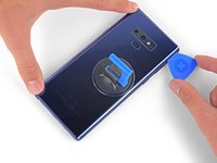
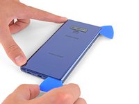
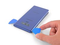
Snijd de lijm door door je openingsplectrum, beginnend in het midden, aan de rechterkant van de telefoon naar boven en naar beneden te schuiven.
-
-
-
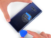
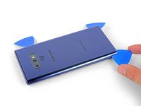
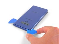
Laat een plectrum in de rechter bovenhoek zitten.
-
Gebruik een andere openingsplectrum om de lijm rondom de rechter onderhoek door te snijden.
-
Laat ook deze plectrum zitten.
There seems to be a lot of glue at the bottom, I broke the glass as I was cutting past the charging port - not sure if it was already fractured or just not enough heat (I used Sellotape so it didn't break up into pieces!)
I think LOTS of heat & patience is the key!
Be very careful around the corners and bottom (probably top too, but I didn't have a problem there). Make sure you've cut in far enough down the side first (go in about 1cm) but less round the corners and work in slowly.
-
-
-
Gebruik een föhn of een warmtepistool of leg een verwarmde iOpener aan de linkerkant van de achterste behuizing gedurende een minuut om de lijm eronder te verzachten.
If using an iOpener it will need to be fully heated and set on for at least 5 minutes. You’ll know the phone is hot enough when its almost too hot to touch.
-
-
-
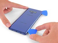
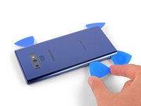
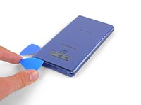
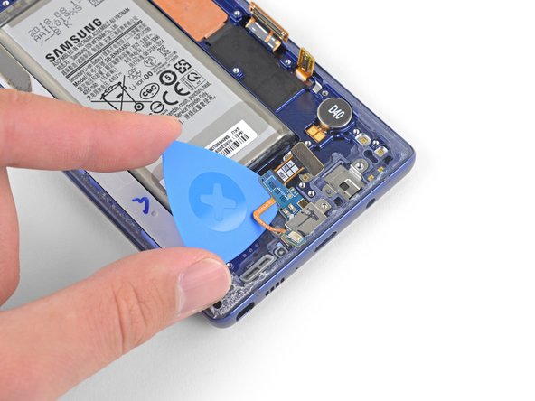
Steek een openingsplectrum in de linker onderhoek van het achterste paneel.
-
Snijd de lijm langs de linkerzijde van het achterste paneel door met een andere plectrum.
Aside from the left edge where the fingerprint sensor cable is, you may have to insert the pick up to 2cm on the sides and top, and a little further along the bottom, and swipe sideways to separate the inner adhesive areas. If one side doesn't separate fully, just apply heat, insert the pick deeper into the phone, and swipe sideways until the back cover detaches. There isn't a need to apply much vertical force, especially on the corners, since the cover will just pop up once all the adhesive has been sliced by the pick.
-
-
-
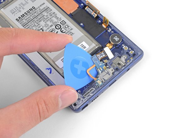
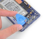
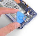
Snijd de lijm langs de linker bovenhoek van het achterste paneel door met behulp van een openingsplectrum.
-
Snijd tot slot de laatste stukjes lijm langs de bovenkant van de telefoon ook door.
Be VERY patient as you slide the opening picks around the periphery of the glass, and use heat very liberally. Make sure the smooth, clear aspect of the iOpener is against the glass, not the rough black portion.
-
-
-
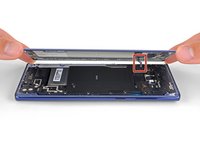
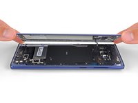
Haal de rechterzijde van de achterste behuizing als eerste los.
-
Kantel de behuizing vanaf de rechterzijde omhoog (en gebruik de linkerzijde als scharnier) om de lintkabel van de vingerafdruksensor bloot te leggen.
Thought I'd done something wrong here as there wasn't a cable attached to the back - the fingerprint reader hadn't come away with the back, but had stayed with the phone.
Exactly the same experience. Made life a little easier.
Happened to me as well.
-
-
-
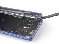
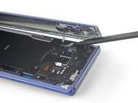
Gebruik de punt van een spudger om de lintkabel van de vingerafdruksensor omhoog en uit het contact te duwen.
-
-
-
Verwijder de achterste behuizing.
-
Gebruik je een pincet om alle lijmresten uit het chassis van de telefoon te halen. Vervolgens maak je deze gebieden schoon met hooggeconcentreerde isopropyl alcohol (minimaal 90%) en een stuk stofvrij doek om het oppervlakte klaar te maken voor nieuwe lijm.
-
Breng de nieuwe lijm voorzichtig in de achterste behuizing aan. Breng vervolgens een kant van het glas langs de zijkant van het chassis van de telefoon aan en druk het glas stevig in de telefoon.
I am installing a new backplate (this is my first repair; I was CERTAIN that I would crack the back glass, and I was NOT wrong) but I’m not sure how tweezers are meant to remove gooey adhesive! I simply used the blue plastic pry tool as a scraper and gently rolled up the goo. Maybe the glue is different because I have a refurbished phone? That may also explain why I had so much trouble with Step 1. Hope that this helps!
Use tweezers remove any inner adhesive strips that may have started peeling off when the back cover is removed, or adhesive clumps. If an adhesive starts to peel off, use tweezers to pull the strip off completely, and then replace only that removed adhesive strip. Actually, the iFixIt inner adhesive strips don't seem to have the white non-stick areas that are on the original adhesive strips. Thus, it seems ok to keep the original inner adhesive strips if still attached to the phone.
The outer adhesive border is like a good, not a strip, and should be replaced. Using isopropyl alcohol to rub off only the edge adhesive on the phone and back cover works well.
After adding a new outer adhesive and reattaching the back cover, you have one try to align and replace the cover. The cover might not attach flush onto the phone with no side gaps, due to the outer adhesive strip placement. It is probably sufficient if the outer adhesive seals all the way around the back cover border.
While testing the phone after battery replacement, but before reattaching the back cover, if a thermal warning (triangular thermometer icon) appears during charging that prevents charging over 50%, remove the charging cable and use a lightly warmed iOpener or heat gun on the battery to warm it slightly. Once the battery is warmed up a little, reattach the charging cable, and the error should go away. Battery charging can be resumed. This assumes no hardware was damaged during battery replacement.
-
-
-
Stap 15 Verwijder het bovenste midframe
Voorzichtig: stappen 15-18 komen van een handleiding die in bewerking is.
-
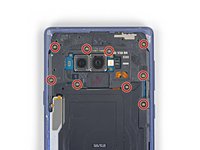
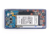
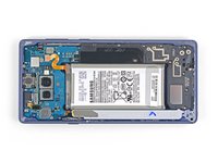
Gebruik een Phillips-schroevendraaier om de negen 4 mm lange schroeven, die het bovenste midframe bevestigen, te verwijderen.
There are two more screws on the bottom right corner of the little side frame that the Qi plate is glued to. I took those out as it put less stress on it.
It helps to hold the fine tweezers with your non-dominant hand to support the screw heads and ensure they come straight out; you can also gently lift as you unscrew.
-
-
-
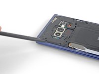
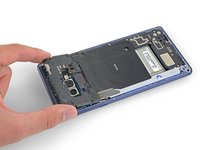
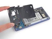
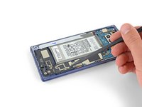
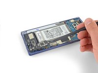
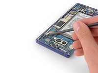
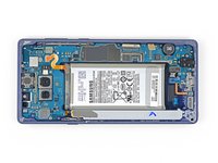
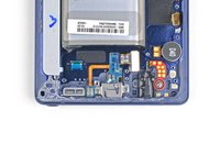
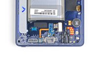
Trek de draadloze oplaadspoel van de batterij, beginnend aan de linkerkant.
-
-
-
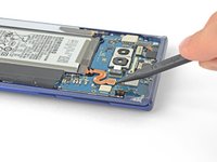
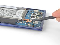
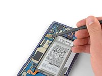
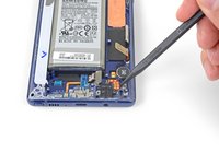
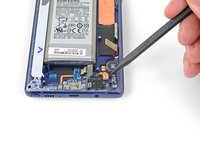
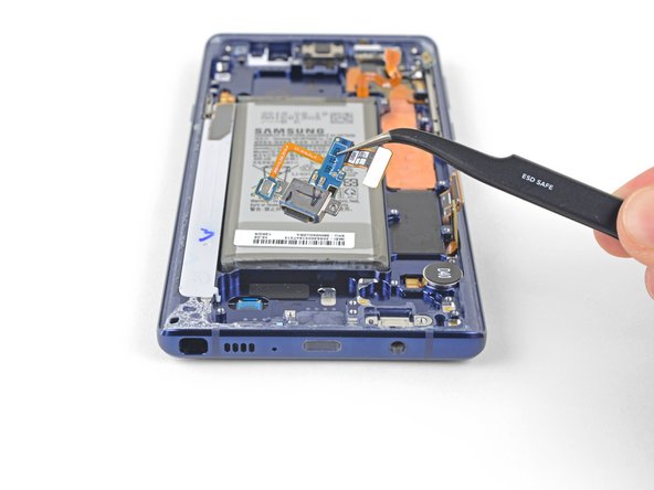
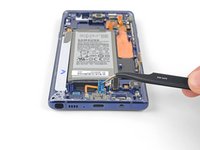
Gebruik de punt van een spudger om de oranje lintkabel, die de batterij aan het moederbord verbindt, los te koppelen.
-
-
-
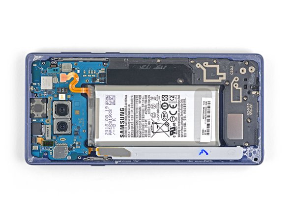
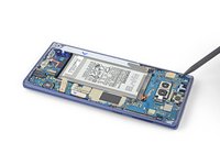
Verwijder de negen 4 mm lange Phillips-schroeven die de plastic cover naast de batterij bevestigen.
-
-
-
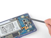
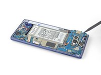
Gebruik de punt van een spudger om de voorste camera-aansluiting in een rechte beweging uit het contact omhoog te duwen.
-
Gebruik een pincet om de voorste camera te verwijderen.
-
-
-
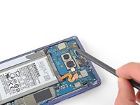
Gebruik de punt van een spudger om de iris-scanner van het moederbord los te koppelen.
-
Gebruik een pincet om de iris-scanner te verwijderen.
-
-
-
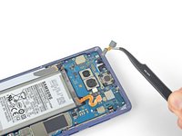
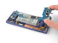
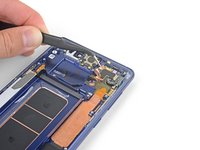
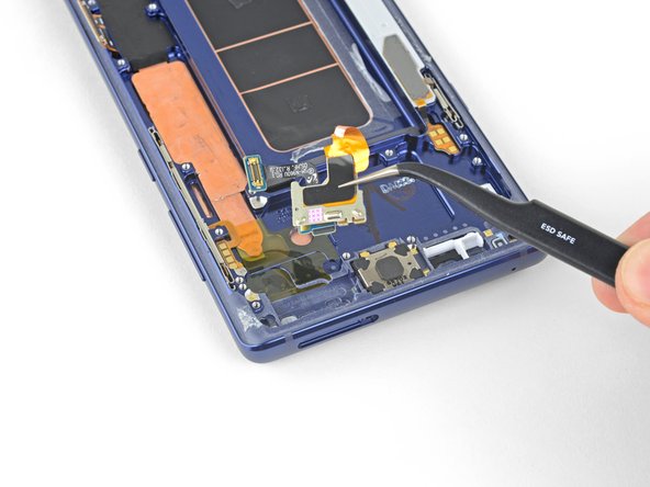
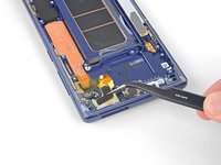
Gebruik het platte einde van een spudger om de voorste sensoraansluiting uit het contact omhoog te duwen.
-
-
-
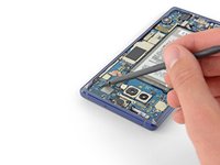
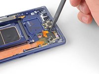
Gebruik het platte einde van een spudger om de schermkabel van het moederbord los te koppelen.
-
-
-
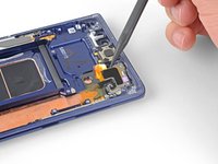
Gebruik het platte einde van een spudger om de oplaadmodule van het moederbord los te koppelen.
These screws are supposed to be 3.2 mm because when I took out these screws, they were shorter than the ones you take out first
-
-
-
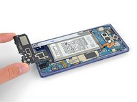
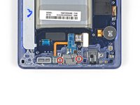
Verwijder de 3.2 mm lange Phillips-schroef uit de hoofdtelefoonjack.
-
-
-
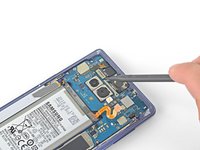
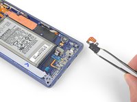
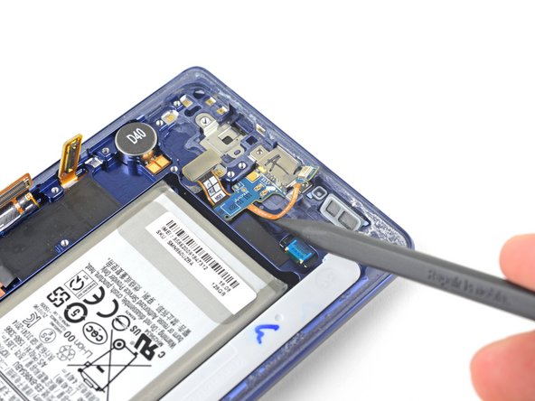
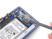
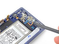
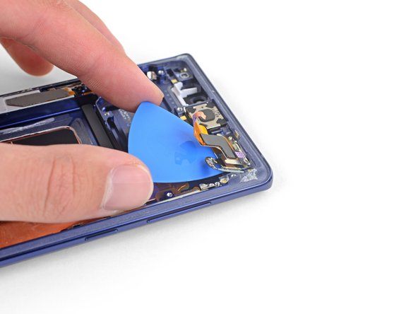
Steek de punt van een spudger in de inkeping naast de contactpunten van de hoofdtelefoonjack.
-
Duw het contactbord in een rechte beweging omhoog om deze los te krijgen van de lijm eronder.
-
-
-
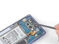
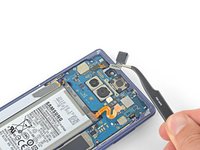
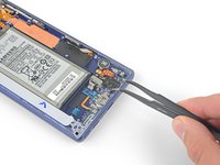
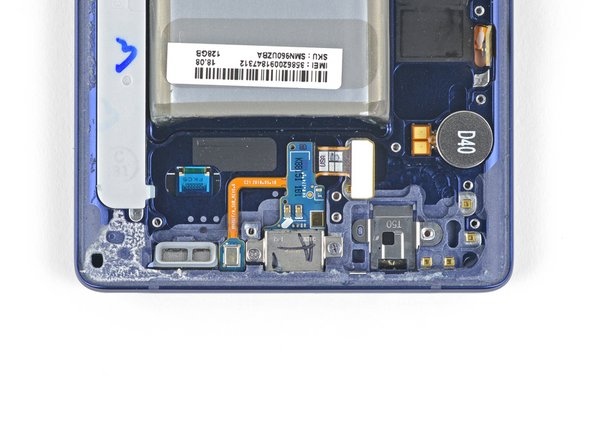
Verwijder de twee 3.2 mm lange Phillips-schroeven uit de oplaadmodule.
Please add a step that mentions the round item labeled “D40”. It, similarly to the headphone jack, is tediously removed by adding some isopropyl alcohol to the groove above/under it and then sliding a spudger or tweezers into the same groove. Slowly wiggle it with your prod while the isopropyl alcohol does its job.
This is necessary If your new display assembly does not include the vibration motor (labeled D40). The pointed end of a spudger may not be small enough to get leverage under it, so use angled tweezers if you have to.
-
-
-
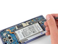
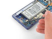
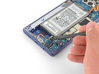
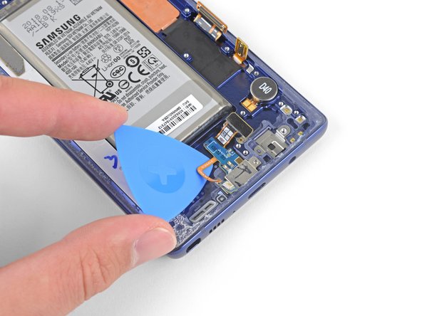
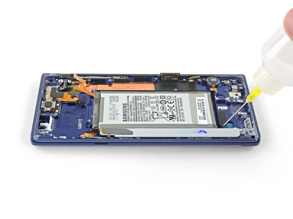
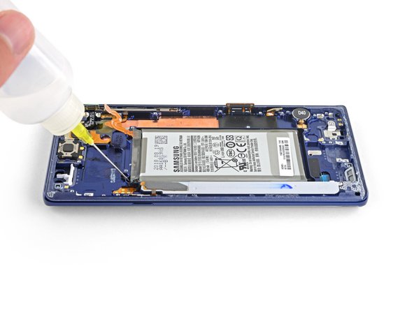
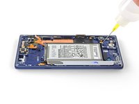
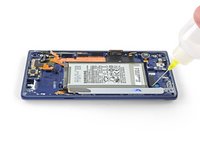
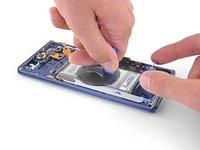
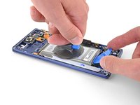
Dien wat druppels isopropyl alcohol (>90%) toe in de opening aan de onderkant en in de linker bovenhoek van de batterij.
-
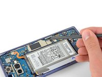
Wacht een aantal minuten zodat de alcohol in kan trekken en de lijm onder de batterij kan verzachten.
-
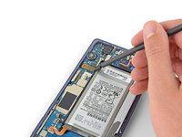
Kantel de telefoon op verschillende manieren zodat de alcohol onder de batterij kan stromen.
-
-
-
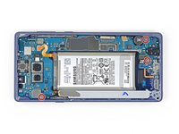
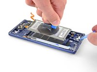
Gebruik een pincet om de koperen folie met kleefstrip los te trekken.
-
Stop met trekken zodra je de sensoropstelling hebt bereikt.
-
-
-
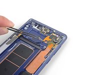
Gebruik een pincet om de voorste sensoropstelling te verwijderen.
Buen día, excelente tutorial...sigan con ese mismo interes...Bendiciones para todo el grupo.
Desde Santa Cruz, Bolivia.
What about the earpiece and the vibration motor?
-


Om je toestel weer in elkaar te zetten, volg je deze instructies in omgekeerde volgorde.
Breng je e-afval naar een door R2 of e-Stewards gecertificeerde recycler.
Ging je reparatie niet zoals gepland? Check dan ons Antwoordenforum voor hulp bij het oplossen van je probleem.
Vergelijk je vervangende onderdeel met het originele onderdeel — het kan zijn dat je meerdere onderdelen mee over moet zetten of beschermlagen voor de lijm moet verwijderen voordat je het nieuwe onderdeel kunt installeren.
Annuleren: ik heb deze handleiding niet afgemaakt.
52 andere personen hebben deze handleiding voltooid.
Met dank aan deze vertalers:
88%

Thomas Keulemans helpt ons de wereld te herstellen! Wil je bijdragen?
Begin met vertalen ›

20Gids Commentaar
Make sure you transfer over the vibration motor if the new frame does not have it… didn’t realize my replacement didn’t have it until I put the glass back on :/
Thank you for pointing this out! I almost missed it! I wish this guide showed how to put it back together instead of just saying “okay now do it again but backwards.” Anyway, I appreciate this comment right here haha.
The guide assumes that you have a new display unit containing all the parts that are left after the last step (display, front glass, screen, cooling system, vibration motor and so on.)
Since replacement parts vary from seller to seller, you’ll have to compare yours to the original and transfer any remaining components. This guide was written for the display assembly that we were selling at the time.
When transferring other components such as the vibration motor just be sure to use the same methods as with similar components. Work slowly, always use heat or ≥90% isopropyl alcohol to soften adhesives, and search the internet for more information as necessary.
But what about the actual replacement of the display screen? The instructions stops at removing the front sensor array
Because it is an OLED screen the entire assembly has to be replaced. If the guide is followed and the part was purchased from iFixit, once the front sensor array is removed you can begin working backwards transferring all components into the new display assembly. Unfortunately replacing the screen from the front is not possible. If you purchase the part from somewhere other than iFixit you may need to transfer additional components.
The guide does not explain how to glue the front and back together once everything is put back together.
Do I have to buy a specific glue or does the new part have pre-applied glue and do I need heat to activate?
Thanks
The new part most likely won’t have pre-installed adhesive. This generic perimeter adhesive guide for Samsung Galaxy phones will help!
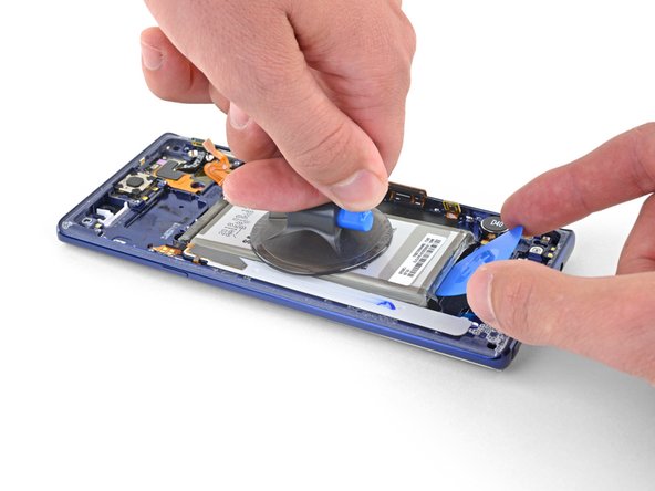
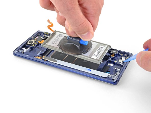
Any suggestions on getting the suction cup to stick to the battery? I cant seem to get mine to hold.
I just flooded the battery space with rubbing alcohol and let it sit for a minute. Then the battery more or less lifted out. If you still think you need it a smaller suction cup or even dental floss to run under the battery may help.
It was very informative and clear. Thank You.
Hello! I would ask, but the display is the same for version 128 or 512gb, right?
I have never had a digitizer not power on. Is it just a bad digitizer or what? I also brought a new battery.
No idea since they won't [and seemingly will never] include reassembly instructions. Thanks for supporting right to repair, but only halfway!
The gasket and adhesive kit came with a great set of components. However it's not clear when and where they are put. Would be nice if iFixit had notes about these for reassembly.
For real because thats literally the ENTIRE POINT. "Now just do it backwards," are TERRIBLE instructions for neurodivergent people like me. Thanks a lot..
Job well done. I take my hat off to the author 🙂👍
Why are there no instructions for how to reassemble the parts to the new Digitizer Screen Assembly?? Thats like, the main part. "Do it all backwards now" is NOT a good instruction. I am baffled by how incomplete this is, given how much good ive heard about Ifixit for years. And this phone and the parts have been out for over half a decade. I am IMMENSELY disappointed in Ifixit right now. This is completely inadequate for a "complete step by step guide." Its not complete, and its only half the steps. Ive always been told "Ifixit will walk you through the whole repair process, step by step!" about pretty much every ifixit guide by multiple friends, multiple news outlets and YouTube channels, including LTT, and yet... you have this. "Okay you removed everything now just do it in reverse." Thanks, my adhd brain is totally not gonna mix things up going backwards and screw something up. Jfc. Please, please, PLEASE actually include FULL instructions in future guides. This sucks for neurodivergent people. A lot.
Because honestly, this just feels incredibly lazy and callous. I get that its a guide for an older phone, but you've had 6 years to fix this. My disappointment can not be adequately quantified with words. I can't just "do it in reverse" with no instructions on how to do that. So I'm stuck with my broken screen because once I take it apart, I won't really know how to reassemble it. And I know that I WILL permanently mess something up without a PROPER guide. I'm not trying to be rude, but this lack of both foresight and hindsight, THAT feels rude. Incredibly rude. Not all of us can just reverse instructions like that, and its both incredibly lazy and insulting that yall would just put "do it in reverse" at the end, and dare to think that is sufficient for everybody. Why would you do that? I genuinely do not understand. My ADHD and Asperger's will not work with "just do it in reverse." Please, do better. P l e a s e
شكرا كانت المعلومه مفيده
Abu Abed - Antwoord