Hi @jllitter ,
I believe that you’re looking at it the wrong way.
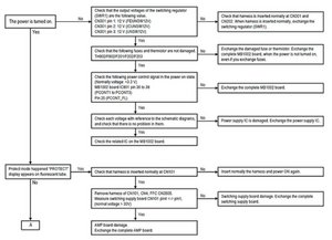
The +32.5V is initially supplied by the switching regulator and IF there is no protect signal in evidence then the enable signal will be sent to the switching regulator.
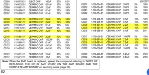
Here are some images taken from the service manual. It is in a mixture of Portuguese and English but you should still be able to read the circuits.
To download the manual, click on the link above and then click on the “I am not a robot Captcha box” below the Document preview box, pass the test and then click on Go to Download. Wait until the sentence This file is downloadable free of charge (5/day): ...processing... changes to This file is downloadable free of charge (5/day): Download (sony bdv-e780w w980w e985w) and then click on Download. Be patient as it takes a little while to find the file.
(click on images to enlarge for better viewing)
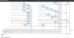
The first image shows the +32.5 V coming from the switching regulator.
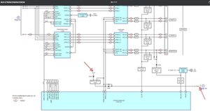
The second image shows the +32.5V being supplied via a zener diode, to the “protect detect circuit”, the output of which goes into the system controller and to the switching regulator.
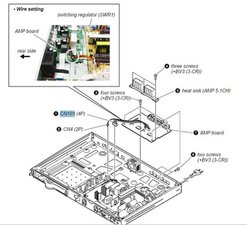
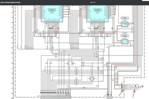
The third image shows the +32.5V volts entering the AMP board from the regulator.
There are no other +32.5V supplies in the device.
Did you try a “cold reset” to check if this has any effect? See p.21 in the manual.


21 opmerkingen
Hi, Have you checked that the vent holes are clear and not clogged up? Can you hear a fan running at all?
door jayeff
The fan works and the device is clean from the inside.
door Jorn
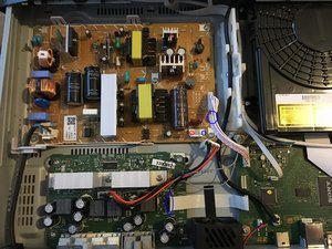
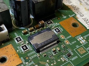
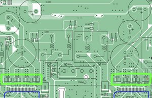
Hi, Take some close up pictures of the systemboard and post back here. There may be some 'stressed' components which might be able to be spotted by someone here. Hopefully someone like @oldturkey03 may even have a service manual or circuit diagram available for it.
Voeg afbeeldingen toe aan een bestaande vraag
door jayeff
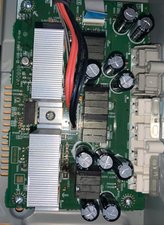
Replaced the AMP board, and the home cinema set is now working.
door Jorn
Also did that. But mine did not work instantly. After consulting a sony repair facility they suggested to check the pins of the flatcable which crosses the fan, because they might be folded. This was the case, so I folded them back and now its working :)
door Floris-Jan
16 commentaren meer tonen