Deze versie kan foutieve bewerkingen bevatten. Schakel over naar de recentste gecontroleerde momentopname.
Wat je nodig hebt
-
Deze stap is niet vertaald. Help het te vertalen
-
Insert a SIM card eject tool, bit, or a straightened paperclip into the small hole in the SIM card tray.
-
Press to eject the tray.
-
-
-
Verwijder de twee 3.5 mm lange pentalobe-schroeven aan de onderkant van de iPhone.
-
-
-
Plaats op 3 mm van de punt van je plectrum een markering met een stift.
-
-
-
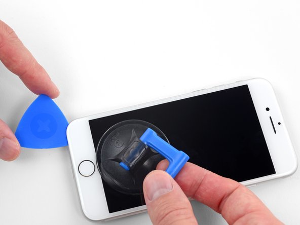
Trek de blauwe hendel naar achteren zodat de anti-klem vrij kan bewegen. (Op deze manier deactiveer je de openingsstand van de anti-klem.)
-
Schuif de armen over de linker- of rechterzijde van je iPhone.
-
Plaats de zuignappen dichtbij de onderkant van de telefoon—één op de voorkant en één aan de achterkant.
-
Druk beide zuignappen aan, om zuigkracht uit te oefenen op de gewenste plek.
-
-
-
Trek het blauwe handvat naar voren om de armen van de anti-klem te vergrendelen.
-
Draai het handvat 360 graden met de klok mee of tot de zuignappen uit beginnen te rekken.
-
Zorg dat de zuignappen op één lijn met elkaar zitten voordat je begint met het openen van het toestel. Als je ziet dat de zuignappen niet meer op één lijn zitten, maak je ze los en breng je ze weer op de juiste positie aan.
-
-
-
Verwarm een iOpener en plaats deze tussen de armen van de anti-klem op je telefoon.
-
Vouw de iOpener zodat deze op de onderkant van de iPhone komt te liggen.
-
Geef de lijm een minuutje de tijd om los te komen zodat de anti-klem een opening kan creëren.
-
Steek een plectrum in de opening onder het scherm.
-
Sla de volgende drie stappen over.
-
-
-
Het verwarmen van de onderkant van de iPhone helpt de lijm, die het scherm op z'n plek houdt, te verzachten, wat het makkelijker maakt om de telefoon te openen.
-
Gebruik een föhn of een warmtepistool, of prepareer een iOpener en leg deze op de onderkant van de iPhone gedurende ongeveer 90 seconden om zo de lijm die eronder zit te verzachten.
-
-
-
Druk een zuignap op de onderste helft van het voorste paneel, net boven de thuisknop.
-
-
-
Verwijder de vier Phillips-schroeven die het plaatje van de onderste schermkabel aan het logic board bevestigen, met de volgende lengtes:
-
Twee 1.3 mm schroeven
-
Twee 2.8 mm schroeven
-
Verwijder het plaatje.
-
-
-
Gebruik de punt van een spudger om de batterijaansluitinguit het contact op het logic board omhoog te duwen.
-
Buig de kabel van de batterijaansluiting voorzichtig weg van het logic board om te voorkomen dat deze per ongeluk contact maakt met het contact en de telefoon inschakelt tijdens de reparatie.
-
-
-
Gebruik de punt van een spudger om de onderste schermaansluiting uit het contact omhoog te duwen.
-
-
-
-
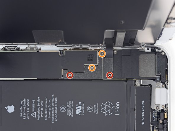
Verwijder de drie schroeven die het plaatje naast de trilmotor bevestigen:
-
Eén 1.3 mm Y000 schroef
-
Eén 2.7 mm Phillips schroef
-
Eén 2.9 mm Phillips schroef
-
-
-
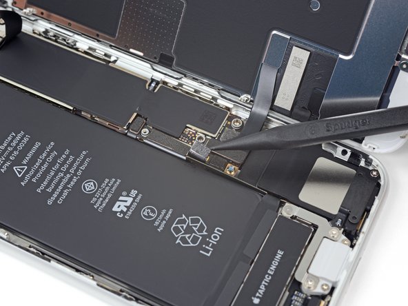
Schuif een openingsplectrum onder de flexkabel van de antenne om het contact laag te houden.
-
Gebruik de punt van je spudger om de flexkabel van de antenne uit het contact omhoog te duwen en los te koppelen, waarbij je je openingsplectrum kunt gebruiken om het contact eronder te houden.
-
-
-
Verwijder de twee schroeven die de trilmotor bevestigen:
-
Eén 2.1 mm Phillips schroef
-
Eén 2.1 mm standoff schroef
-
-
-
Verwijder de twee schroeven die de barometrische ventilator aan de achterste behuizing bevestigen:
-
Eén 2 mm lange Phillips schroef
-
Eén 1.8 mm lange Phillips schroef
-
-
Deze stap is niet vertaald. Help het te vertalen
-
Use the flat end of a spudger to disconnect the camera cable connector by prying it straight up from its socket.
-
-
Deze stap is niet vertaald. Help het te vertalen
-
Remove the two screws securing the rear-facing camera bracket:
-
One 3.0 mm standoff screw
-
One 3.1 mm Phillips screw
-
-
Deze stap is niet vertaald. Help het te vertalen
-
Use the point of a spudger to disconnect the flash connector from its socket by prying it straight up.
-
-
Deze stap is niet vertaald. Help het te vertalen
-
Remove the two screws securing the upper cable bracket:
-
One 2.9 mm Phillips screw
-
One 1.3 mm Phillips screw
-
-
Deze stap is niet vertaald. Help het te vertalen
-
Use the flat end of a spudger to pry the upper cable connector up from its socket.
-
-
Deze stap is niet vertaald. Help het te vertalen
-
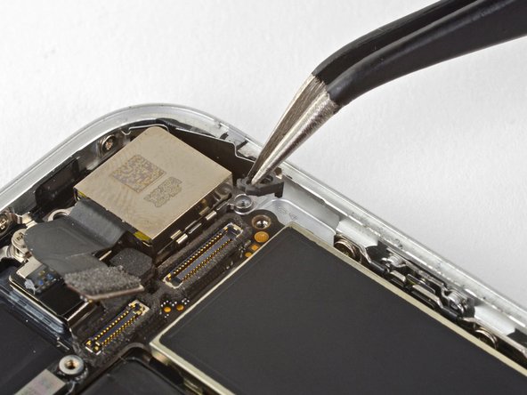
Remove the three Phillips 1.3 mm screws securing the top left antenna component.
-
-
Deze stap is niet vertaald. Help het te vertalen
-
Remove the 1.4 mm Phillips screw securing the antenna component to the top of edge of the case.
-
-
Deze stap is niet vertaald. Help het te vertalen
-
Remove the two Phillips screws securing the grounding clip at the top left edge of the logic board:
-
One 1.5 mm Phillips screw
-
One 2.6 mm Phillips screw
-
-
Deze stap is niet vertaald. Help het te vertalen
-
Remove the three screws securing the motherboard:
-
One 1.8 mm Phillips screw
-
One 2.5 mm standoff screw
-
One 2.2 mm standoff screw
-
-
Deze stap is niet vertaald. Help het te vertalen
-
Use tweezers to gently bend the logic board grounding bracket out of the way.
-
-
Deze stap is niet vertaald. Help het te vertalen
-
Use the point of a spudger to move the SIM card eject plunger out of the logic board's way.
-
-
Deze stap is niet vertaald. Help het te vertalen
-
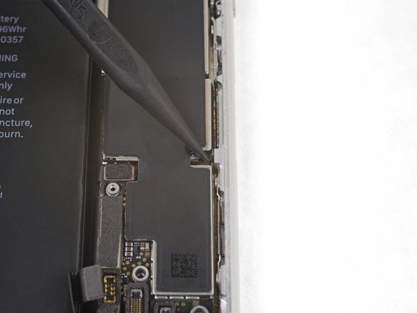
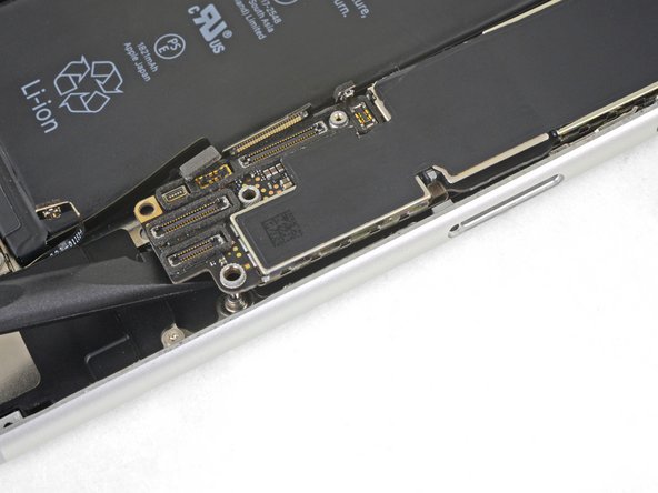
Use the point of a spudger to pry up and disconnect the Lightning connector cable from the logic board.
-
-
Deze stap is niet vertaald. Help het te vertalen
-
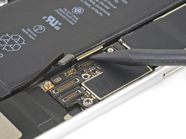
Use the point of a spudger to pry up and disconnect the wireless charging coil connector.
-
-
Deze stap is niet vertaald. Help het te vertalen
-
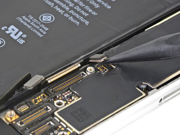
Use the flat end of a spudger to gently lift the battery connector end of the logic board up.
-
-
Deze stap is niet vertaald. Help het te vertalen
-
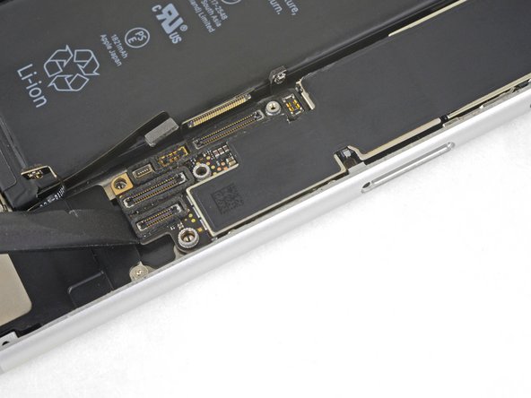
Grasping it by the edges, lift the logic board near the battery connector and remove it.
-
-
Deze stap is niet vertaald. Help het te vertalen
-
Remove the two screws securing the speaker to the rear case:
-
One 1.5 mm Phillips screw
-
One 2.1 mm Phillips screw
-
-
Deze stap is niet vertaald. Help het te vertalen
-
Remove the three screws securing the Lightning connector cable in place:
-
One 1.3 mm Phillips screw
-
Two 2.2 mm Phillips screws
-
-
Deze stap is niet vertaald. Help het te vertalen
-
Remove the two 1.4 mm Phillips screws securing the Lightning port to the bottom edge of the phone.
-
-
Deze stap is niet vertaald. Help het te vertalen
-
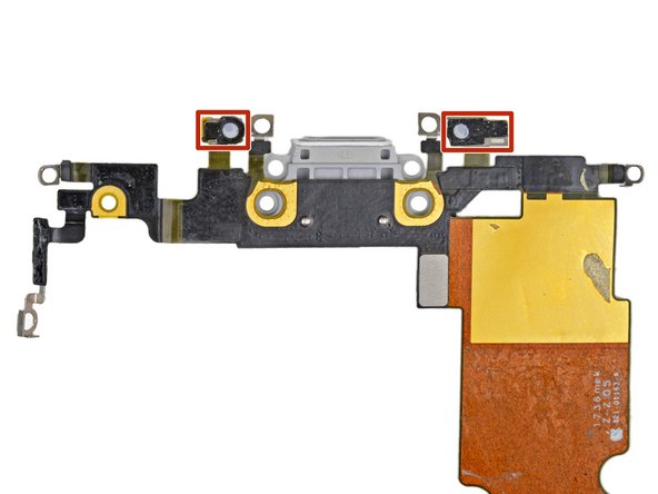
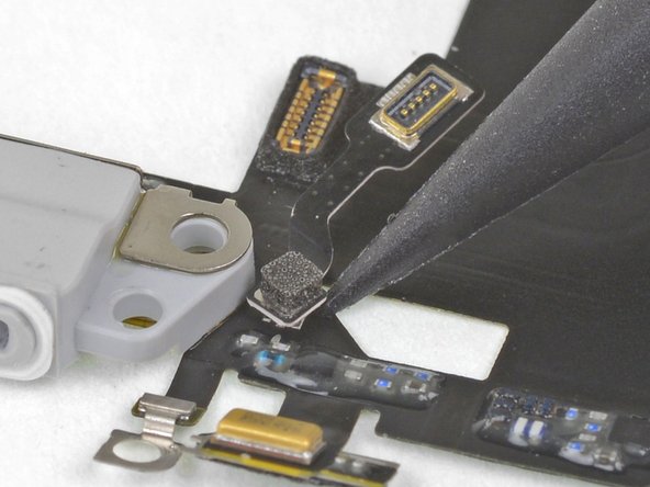
Use the point of a spudger to gently pry the logic-board-side microphone free from the adhesive securing it in place.
-
-
Deze stap is niet vertaald. Help het te vertalen
-
Use the point of a spudger to gently pry the battery-side microphone free from the adhesive securing it in place.
-
-
Deze stap is niet vertaald. Help het te vertalen
-
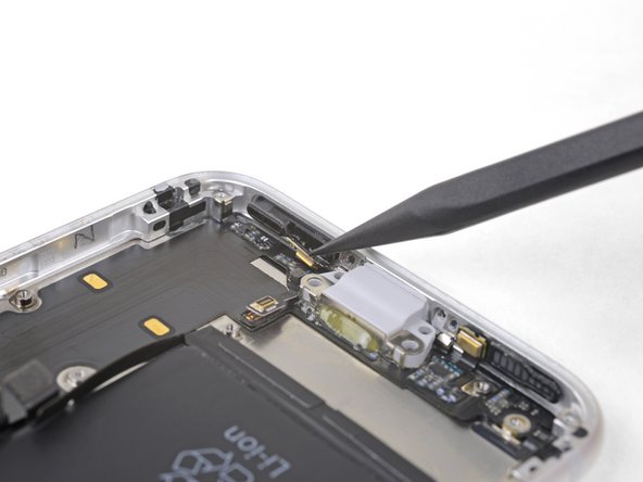
Apply a heated iOpener to the bottom of the phone, angling it as shown. This will help loosen the flex cable adhesive.
-
-
Deze stap is niet vertaald. Help het te vertalen
-
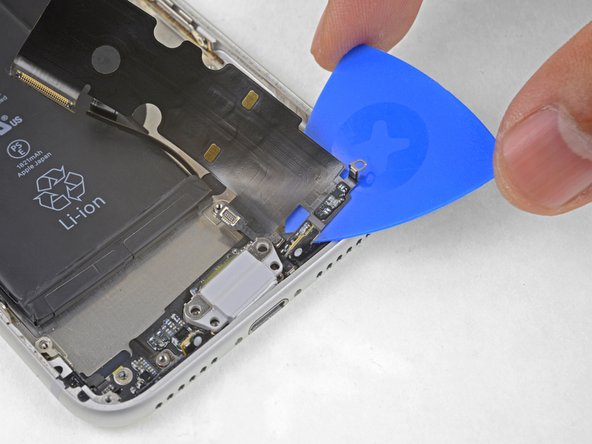
Slide an opening pick underneath the top portion of the Lightning connector assembly flex cable, and begin separating the cable from the rear case.
-
Gently slide the pick toward the outside edge of the iPhone (away from the battery).
-
-
Deze stap is niet vertaald. Help het te vertalen
-
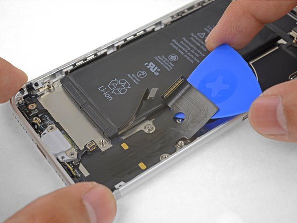
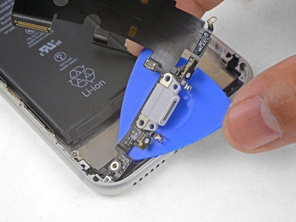
Continue separating the upper portion of the flex cable, being careful not to damage any other components along the way.
-
Stop sliding the pick once it passes the lower edge of the battery.
-
-
Deze stap is niet vertaald. Help het te vertalen
-
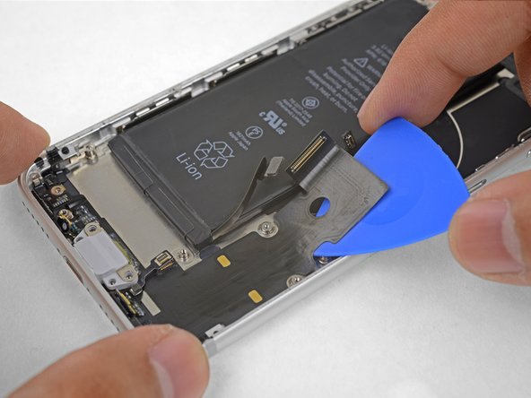
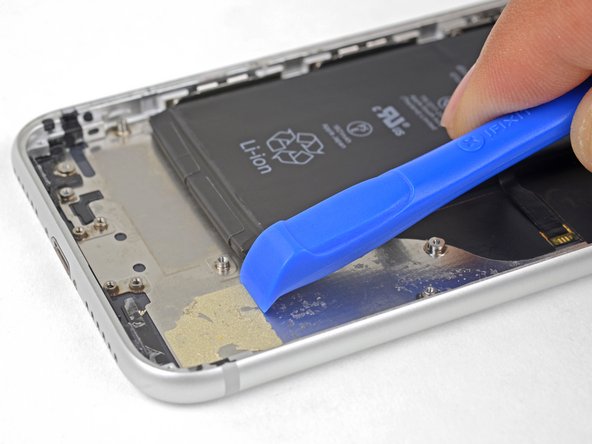
Starting at the corner of the phone, slide the pick underneath the cable towards the Lightning connector.
-
Stop sliding the pick when it reaches the Lightning connector.
-
-
Deze stap is niet vertaald. Help het te vertalen
-
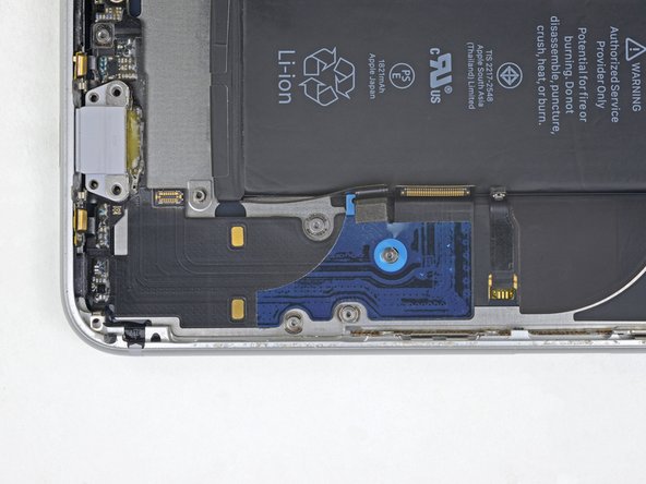
Gently pull the Lightning connector out of its hole on the rear case.
-
-
Deze stap is niet vertaald. Help het te vertalen
-
Slide an opening pick below the Lightning connector to further separate the assembly from the rear case.
-
Continue to slide the pick until the Lightning connector assembly is no longer adhered to the bottom of the rear case.
-
-
Deze stap is niet vertaald. Help het te vertalen
-
Slide an opening pick between the left edge of the case and the remaining adhered section of the Lightning assembly.
-
-
Deze stap is niet vertaald. Help het te vertalen
-
Remove the Lightning connector assembly.
-
Use a plastic tool to scour any bits of adhesive residue from the rear case. You can use some high concentration isopropyl alcohol to help clean the surface.
-
-
Deze stap is niet vertaald. Help het te vertalen
-
The small adhesive patch on the bottom of each microphone also protects your iPhone from liquid and dust intrusion. For best results, replace the two adhesive patches before installing your Lightning connector assembly.
-


Annuleren: ik heb deze handleiding niet afgemaakt.
109 andere personen hebben deze handleiding voltooid.


29 opmerkingen
I love how you mention the “antenna converter cable” twice but never show what the &&^& that part even looks like??
Sorry about that! It’s actually shown in the 3rd image in the last step. I cropped the photo so that it’s zoomed in more to show it.
I would HIGHLY recommend not attempting this fix. I have done a variety of repairs on iPhones (screens, batteries, etc.) and decided to try this to address a broken microphone. I could make regular phone calls but couldn’t use speakerphone or FaceTime. After replacing the lightening charger using the instructions and the iFixit parts, I still can’t use the speakerphone or FaceTime function. To make matters worse, my phone won’t charge through the lightening connector, won’t wirelessly charge, and people can’t hear me even when I make a regular phone call anymore. In other words, I started with one fairly minor problem and, due to this repair, have a whole bunch of new (much more significant) issues. Don’t make the same mistake I did.
Don’t know about the charging issues, but the reason replacing the microphone didn’t help is because you replaced the wrong microphone.
iPhone 8 has 3 mics.
- One for regular phone calls - which is the one you replaced
- One for the front-facing camera - which is used for the speakerphone and FaceTime and is located near the earpiece
- One for the back-facing camera
Excelente guía..!!