
Dell 1350cnw Fuser Unit Replacement
Inleiding
Ga naar stap 1The fuser unit is located at the top of the printer, and bonds the powdered toner onto the paper through applying high temperature and pressure. If this unit isn't working, this guide will show how to access and replace it.
Wat je nodig hebt


-
-
Insert prying tool behind each end of the plastic strip. Pry outwards to unclip and pull the ends forwards away from the printer.
-
Note - Unclipping the right-hand end requires opening the toner cover for access.
-
-
-
Insert prying tool between the front band and top cover of the printer, and pry forwards to release the clips holding the top edge in place.
-
-
-
Tilt the top of the front band away from the printer and lift away to remove.
-
-
-
Unclip the back end of the plastic trim by prying away from the printer back panel.
-
Pull the trim piece towards the back of the printer.
-
Tilt the top edge away from the printer and lift away to remove.
-
-
-
Pry up front edge of the control panel module to unclip.
-
Lift up front edge and pull module forwards slightly to unhook rear edge.
-
Pull out cable connector to unplug the display/ control panel module.
-
-
-
Remove the front lower flap by carefully bending in the middle and pulling out the locating pins one end at a time.
-
-
-
Remove both 7mm phillips screws securing the front cover in place.
-
-
-
-
Unclip the three clips along each end of the front cover by prying outwards and forwards with a prying tool as shown.
-
-
-
Slide out the bottom edge away from the printer and pull the front cover down away from the top edge to remove.
-
-
-
Undo both the 5mm M3 phillips screws holding the top cover brackets to the chassis.
-
-
-
Pull the top cover brackets forwards off the metal frame and lift up to loosen the front edge of the top cover.
-
-
-
Pry the top cover clip off the locating peg at the back of the printer, and lift up the top cover corner.
-
-
-
Pry apart the back edge of the top cover and the back cover of the printer to unclip the top cover.
-
-
-
Lift up the top cover from the control panel corner, pulling towards the back right-hand corner.
-
Note - The top cover should unclip from the back corner with the corner/side piece still attached.
-
-
-
Unclip the back edge of the side cover by prying away from the printer back panel.
-
Pull the top of the side panel away from the printer.
-
Lift up the printer from underneath to release the bottom clips, and the side panel drops away from the printer.
-
-
-
Remove the four 7mm phillips screws holding the rear cover to the printer.
-
-
-
Pull out the connector for the rear cover sensor from the power supply board.
-
De-route the light pink coloured pair of sensor cables and remove from the wiring harness.
-
-
-
Unclip the rear cover opposite the de-routed cables by prying away from the rest of the printer using a prying tool.
-
The rear cover can now be removed from the printer.
-
-
-
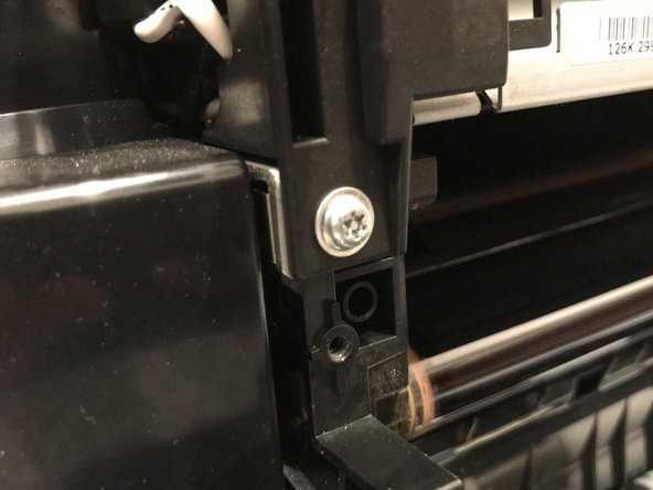
Unscrew the 9mm phillips screw.
-
Unscrew the 9mm Torx TR10 security screw.
-
-
-
Unplug the fuser power cable by squeezing the top of the retaining clip and pulling the connector up from the power supply board.
-
De-route the fuser power cable and remove from the cable restraint.
-
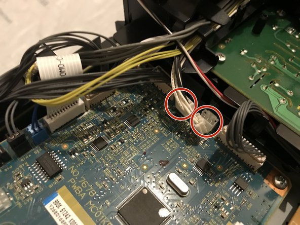
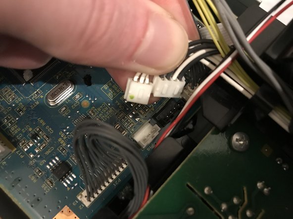
Pull up on the two fuser unit control cable connectors to unplug from the control board.
-
De-route the two sets of control cables from the control board to the fuser unit and remove from the wiring harness.
-


To reassemble your device, follow these instructions in reverse order.
To reassemble your device, follow these instructions in reverse order.