
Internal computer bus interfaces
The internal computer bus interface defines the physical and logical means by which internal drives (such as hard disks, optical drives, ...) connects to the PC. A modern PC uses one or both of the following interfaces:
Types of computer bus interfaces
Serial ATA (SATA)
Serial ATA (SATA) is a newer technology that is replacing ATA. SATA has several advantages over ATA, including smaller cables and connectors, higher bandwidth, and greater reliability. Although SATA and ATA are incompatible at the physical and electrical levels, adapters are readily available that allow SATA drives to be connected to ATA interfaces and vice versa. SATA is generally compatible with ATA at the software level, which means that the operating system ATA drivers work with either SATA or ATA interfaces and hard drives. Figure 7-2 shows two SATA interfaces, above and below the 32.768 kHz clock crystal at center. Note that each interface connector is keyed with an L-shaped body, which prevents the SATA cable from being connected backward.
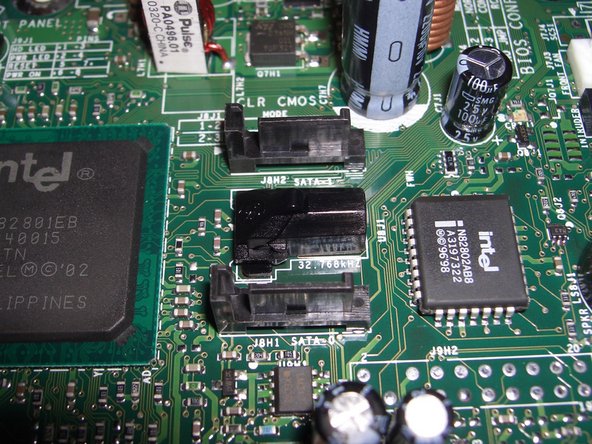
Figure 7-2: SATA interfaces
Small Computer System Interface (SCSI)
The Small Computer System Interface (SCSI) is usually pronounced scuzzy, but sometimes sexy. SCSI is used in servers and high-end workstations, where it provides two advantages: improved performance relative to ATA and SATA in multitasking, multiuser environments, and the ability to daisy-chain many drives on one interface. Although we formerly recommended SCSI for high-performance desktop systems, the very high cost of SCSI drives and host controllers and the narrowing performance gap between SCSI and SATA has led us to withdraw that recommendation.
AT Attachment (ATA)
AT Attachment (ATA), pronounced as individual letters, was by far the most common hard disk interface used in PCs from the early 1990s through 2003. ATA is sometimes called Parallel ATA or PATA, to differentiate it from the newer Serial ATA (SATA) interface. ATA is still used in new systems, although it is being superseded by SATA. ATA is also often called IDE (Integrated Drive Electronics). Figure 7-1 shows two standard ATA interfaces, located at their usual position on the front edge of a motherboard. Note that each interface connector is keyed with a missing pin in the top row and a notch in the connector shroud at the bottom.

Figure 7-1: Standard ATA interfaces
ATA VERSUS ATAPI
Technically, only hard drives are ATA devices. Optical drives, tape drives, and similar devices that connect to ATA interfaces use a modified version of the ATA protocols called ATAPI (ATA Packet Interface). In practical terms, it makes little difference, as you can connect either an ATA hard drive, an ATAPI device, or both at the same time to any ATA interface.
Types of ATA cables
All desktop ATA cables have three 40-pin connectors: one that connects to the ATA interface and two that connect to ATA/ATAPI drives. ATA cables come in three varieties:
Standard
A standard ATA cable uses a 40-wire ribbon cable and 40-pin connectors in all three positions. All 40 conductors connect to all three connectors. The only real variation, other than cable quality, is the positioning of the three connectors. The two device connectors on a standard ATA cable are located nearer one end of the cable. Either drive may be connected to either drive connector. A standard ATA cable may be used with any ATA/ATAPI device through UltraATA-33 (UDMA Mode 2). If a standard ATA cable is used to connect an UltraATA-66 (UDMA Mode 4) or faster device, that device functions properly, but falls back to operating in UDMA Mode 2 (33 MB/s). A standard ATA cable requires setting master/slave jumpers for connected devices.
Note that the standard ATA cables aren't that "standard" anymore btw (since these are now all ready quite old). Most computers that still have ATA interfaces will probably be of the UltraDMA type.
Standard/CSEL
A standard/CSEL ATA cable is identical to a standard ATA cable except that pin 28 is not connected between the middle drive connector and the end drive connector. A standard/CSEL ATA cable supports either master/slave jumpering or CSEL jumpering for connected devices. Connector position is significant on a standard/CSEL cable. The interface connector on a CSEL cable is either labeled or is a different color than the drive connectors. The center connector is for the master device, and the end connector opposite the interface connector is for the slave device.
UltraDMA (80-wire)
An UltraDMA (UDMA) cable uses an 80-wire ribbon cable and 40-pin connectors in all three positions. The additional 40 wires are dedicated ground wires, each assigned to one of the standard 40 ATA pins. A UDMA cable may be used with any ATA/ATAPI device and should be for more reliable functioning but is required for best performance with UltraATA-66, -100, and -133 devices (UDMA Modes 4, 5, and 6, respectively). All UDMA cables are CSEL cables, and may be used in either cable select mode or master/slave mode. Color-coded connectors were not specified for earlier ATA cables.
Because an UltraDMA cable is required for UltraATA-66 or faster operation, the system must have a way to detect if such a cable is installed. This is done by grounding pin 34 in the blue connector, which attaches to the interface. Because 40-wire ATA cables do not ground pin 34, the system can detect at boot whether a 40-wire or 80-wire cable is installed.
A SHEEP IN WOLF'S CLOTHING
Keep unlabeled 40-wire CSEL cables segregated from standard cables. If you substitute a CSEL cable for a standard cable, drives that are jumpered as master or slave function properly. If you substitute a standard cable for a CSEL cable and connect one drive jumpered as CSEL to that cable, it will function properly as master. But if you connect two CSEL drives to a standard cable, both function as master, which may result in anything from subtle problems to (more likely) the system being unable to access either drive. The best rule is simply never to use a 40-wire cable to connect a hard drive.
ALL CSEL CABLES ARE NOT THE SAME
Note the difference between using a 40-wire CSEL cable and an 80-wire cable for CSEL operation. Although all Ultra DMA cables support drives jumpered as either master/slave or CSEL, that does not mean you can freely substitute an 80-wire cable for a 40-wire cable. If the drives are jumpered as master/slave, substituting an 80-wire cable works fine. However, if the drives are jumpered as CSEL, replacing a 40-wire CSEL cable with an 80-wire cable causes the drives to exchange settings. That is, the drive that was master on the 40-wire cable becomes slave on the 80-wire cable, and vice versa.
PIO Mode Versus DMA Mode
ATA defines two classes of transfer mode, called PIO Mode (Programmed I/O Mode) and DMA Mode (Direct Memory Access Mode). PIO mode transfers are much slower and require the processor to arbitrate transfers between the device and memory. DMA mode transfers are much faster and occur without processor intervention. If either device on an ATA channel uses a PIO mode, both devices must do so. That cripples throughput and puts a heavy load on the processor, bogging down the system whenever the drive is accessed.
All modern ATA and ATAPI devices support DMA mode, but for backward compatibility, most can be set to use PIO mode. Using PIO mode is a mistake. When you upgrade a system, if you find any drives that support only PIO mode, replace them. Only very old hard drives and optical drives are limited to PIO mode anyway, so replacing them is a no-brainer.
Compatibility Between Old and New IDE Devices
With minor exceptions, there are no outright compatibility conflicts between new ATA devices and old ATA interfaces or vice versa. Newer drives cannot yield their highest performance when connected to an old ATA interface, just as a new interface can't improve the performance of an older drive. But you can connect any ATA or ATAPI drive to any ATA interface with assurance that it will function, albeit perhaps not optimally.
That said, you should not use elderly PIO devices on the same interface as a DMA device. Both devices will function, but the throughput of the DMA device will be crippled. If you're upgrading a system that has a PIO mode device installed, if possible reconfigure it for DMA. Otherwise, replace it with a DMA-capable device.
Also note that an interface supports only one DMA or UltraDMA (UDMA) mode at a time. For example, if you connect a UDMA Mode 4 (66.6 MB/s) Plextor PX-716A DVD writer and a UDMA Mode 6 (133 MB/s) Maxtor hard drive to the same ATA interface, the hard drive operates in UDMA Mode 4 at 66 MB/s, which may hamper hard drive throughput. Similarly, if you install a Plextor PX-740A DVD writer, which supports UDMA Mode 2 (33 MB/s) as its fastest mode, hard drive throughput is crippled at only 33 MB/s.
Master and slave
Before SATA interfaces and drives became common, ATA was used almost universally to connect hard drives. Even today, hundreds of millions of PCs have ATA hard drives. That number will inevitably decline as older systems are upgraded and replaced, but ATA will remain with us for years.
The original ATA specification defined a single interface that supported one or two ATA hard drives. By the early 1990s, nearly all systems had dual ATA interfaces, each of which supported up to two ATA hard drives or ATAPI devices. Ironically, we've come full circle. Many current motherboards provide several SATA interfaces, but only one ATA interface.
If a system has two ATA interfaces, one is defined as the primary ATA interface and the other as the secondary ATA interface. These two interfaces are identical functionally, but the system assigns a higher priority to the primary interface. Accordingly, the hard drive (a high-priority peripheral) is usually connected to the primary interface, with the secondary interface being used for optical drives and other lower-priority devices.
MASTERS ARE MASTERS, AND SLAVES ARE SLAVES
When you jumper a device master or slave, the device assumes that role regardless of which position it connects to on the ATA cable. For example, if you jumper a device as master, it functions as master regardless of whether it is attached to the drive connector at the end of the ATA cable or the drive connector in the middle of the ATA cable.
Assigning masters and slaves
Each ATA interface (often loosely called an ATA channel) can have zero, one, or two ATA and/or ATAPI devices connected to it. Every ATA and ATAPI device has an embedded controller, but ATA permits (and requires) only one active controller per interface. Therefore, if only one device is attached to an interface, that device must have its embedded controller enabled. If two devices are attached to an ATA interface, one device must have its controller enabled and the other must have its controller disabled.
In ATA terminology, a device whose controller is enabled is called a master; one whose controller is disabled is called a slave (ATA predates Political Correctness). In a PC with two ATA interfaces, a device may therefore be configured in any one of four ways: primary master, primary slave, secondary master, or secondary slave. ATA/ATAPI devices are assigned as master or slave by setting jumpers on the device, as shown in Figure 7-3.

Figure 7-3: Setting the master/slave jumper on an ATA drive
Master/slave guidelines
When deciding how to allocate devices between two interfaces and choose master or slave status for each, use the following guidelines:
- Always assign the main hard drive as primary master. Do not connect another device to the primary ATA interface unless both positions on the secondary interface are occupied.
- ATA forbids simultaneous I/O on an interface, which means that only one device can be active at a time. If one device is reading or writing, the other device cannot read or write until the active device yields the channel. The implication of this rule is that if you have two devices that need to perform simultaneous I/O for example, a DVD writer that you use to duplicate DVDs from a DVD-ROM drive you should place those two devices on separate interfaces.
- If you are connecting an ATA device (a hard drive) and an ATAPI device (for example, an optical drive) to the same interface, set the hard drive as master and the ATAPI device as slave.
- If you are connecting two similar devices (ATA or ATAPI) to an interface, it generally doesn't matter which device is master and which slave. There are exceptions to this guideline, however, particularly with ATAPI devices, some of which really want to be master (or slave) depending on which other ATAPI device is connected to the channel.
- If you are connecting an older device and a newer device to the same ATA interface, it's generally better to configure the newer device as master, because it is likely to have a more capable controller than the older device.
- Avoid sharing one interface between a DMA-capable device and a PIO-only device. If both devices on an interface are DMA-capable, both use DMA. If only one device is DMA-capable, both devices are forced to use PIO, which reduces performance and increases CPU utilization dramatically. Similarly, if both devices are DMA-capable, but at different levels, the more capable device is forced to use the slower DMA mode. Replace any PIO-only devices if possible.
Connecting the drive to the correct connector
To be able to determine the correct jumper setting, you need to make sure you connect the drive to the correct connector.
With standard ATA cables
For standard ATA cables, here's how it works:
All connectors are black. Either drive may be connected to either drive connector. Generally, you place the master device at the middle connector of the cable, and put the slave at the end of the cable. See here
With Cable Select cables
Most ATA/ATAPI drives provide a Cable Select (CS or CSEL) jumper in addition to the standard master/slave jumpers. If you jumper a drive as master (or slave), that drive functions as master (or slave) regardless of which connector it is attached to on the ATA cable. If you jumper a drive as CSEL, the position of the drive on the cable determines whether the drive functions as a master or a slave.
CSEL was introduced as a means to simplify ATA configuration. The goal was that drives could simply be installed and removed without changing jumpers, with no possibility of conflict due to improper jumper settings. Although CSEL has been around for many years, only in the last few years has it become popular with system makers.
Using CSEL requires the following:
- If one drive is installed on the interface, that drive must support and be configured to use CSEL. If two drives are installed, both must support and be configured to use CSEL
- The ATA interface must support CSEL. Very old ATA interfaces do not support CSEL, and treat any drive configured as CSEL as a slave.
- The ATA cable must be a special CSEL cable. Unfortunately, there are three types of CSEL cable:
- A 40-wire CSEL cable differs from a standard 40-wire ATA cable in that pin 28 is connected only between the ATA interface and the first drive position on the cable (the middle connector). Pin 28 is not connected between the interface and the second drive position (the end connector on the cable). With such a cable, the drive attached to the middle connector (with pin 28 connected) is master; the drive attached to the connector furthest from the interface (with pin 28 not connected) is slave.
- All 80-wire (Ultra DMA) ATA cables support CSEL, but with exactly the opposite orientation of the 40-wire standard CSEL cable just described. With such a cable, the drive attached to the middle connector (with pin 28 not connected) is slave; the drive attached to the connector furthest from the interface (with pin 28 connected) is master. This is actually a better arrangement, if a bit non-intuitive how can a wire be connected to the end connector but not to the one in the middle? because the standard 40-wire CSEL cable puts the master drive on the middle connector. If only one drive is installed on that cable, that leaves a long "stub" of cable hanging free with nothing connected to it. Electrically, that's a very poor idea, because an unterminated cable allows standing waves to form, increasing noise on the line and impairing data integrity.
- A 40-wire CSEL Y-cable puts the interface connector in the middle with a drive connector on each end, one labeled master and one slave. Although this is a good idea in theory, in practice it seldom works. The problem is that ATA cable length limits still apply, which means that the drive connectors don't have enough cable to get to the drives in all but the smallest cases. If you have a tower, you can forget it.40-wire CSEL cables are supposed to be clearly labeled, but we have found that this is often not the case. It is not possible to identify such cables visually, although you can verify the type using a digital voltmeter or continuity tester between the two end connectors on pin 28. If there is continuity, you have a standard ATA cable. If not, you have a CSEL cable.
With UltraDMA cables
The Ultra DMA cable specification requires the following connector colors:
- One end connector is blue, which indicates that it attaches to the motherboard ATA interface.
- The opposite end connector is black, and is used to attach the master drive (Device 0), or a single drive if only one is attached to the cable. If CSEL is used, the black connector configures the drive as master. If standard master/slave jumpering is used, the master drive must still be attached to the black connector, because ATA-66, ATA-100, and ATA-133 do not allow a single drive to be connected to the middle connector, which results in standing waves that interfere with data communication.
- The middle connector is gray, and is used to attach the slave drive (Device 1), if present.
Figure 7-4 shows an 80-wire UltraDMA cable (top) and a 40-wire standard ATA cable for comparison.

Figure 7-4: UltraDMA 80-wire ATA cable (top) and standard 40-wire ATA cable
Setting jumpers
ATA devices have some or all of the following jumper selections:
Master
Connecting a jumper in the master position enables the on-board controller. All ATA and ATAPI devices have this option. Select this jumper position if this is the only device connected to the interface, or if it is the first of two devices connected to the interface.
Slave
Connecting a jumper in the slave position disables the on-board controller. (One of our technical reviewers notes that he has taken advantage of this to retrieve data from a hard drive whose controller had failed, a very useful thing to keep in mind.) All ATA and ATAPI devices can be set as slave. Select this jumper position if this is the second device connected to an interface that already has a master device connected.
Cable Select
Most ATA/ATAPI devices have a third jumper position labeled Cable Select, CS, or CSEL. Connecting a jumper in the CSEL position instructs the device to configure itself as master or slave based on its position on the ATA cable. If the CSEL jumper is connected, no other jumpers may be connected. For more information about CSEL, see the following section.
Sole/Only
When functioning as master, a few older ATA/ATAPI devices need to know whether they are the only device on the channel, or if a slave device is also connected. Such devices may have an additional jumper position labeled Sole or Only. For such a device, jumper it as master if it is the master device on the interface, slave if it is the slave device on the interface, and sole/only if it is the only device connected to the interface.
Slave Present
A few older drives have a jumper designated Slave Present, or SP. This jumper performs the inverse function of the sole/only jumper, by notifying a device jumpered as master that there is also a slave device on the channel. For such a device, jumper it as master if it is the only device on the interface, or slave if it is the second of two devices on the interface.
If it is the master on a channel that also has a slave installed, connect both the master and slave present jumpers.
BIOS Setup
After you connected your drives to the right connectors on the cables, and set the jumpers, it's time to let the system detect the drives. For this, restart the system and run BIOS Setup (you'll need to press a key as your system is booting up; often the key is either F1, F2, Esc or Del). In the menu, look for an option named Auto Detect or something similar, if the BIOS doesn't automatically show your drives. Use this Auto Detect option to force drive detection. Reboot and you should be able to use your drives (you can then start to partition and format your drive). If you are unable to get your drives working using the current configuration, try other configurations as explained here
Note that the BIOS Setup will also tell you the number of your SATA interfaces, if you have SATA. This will be useful to let you determine on which interface you have to connect your drive to make it the primary drive.
Serial ATA
Serial ATA (also known as SATA or S-ATA) is the successor to the older ATA/ATAPI standards. SATA is intended primarily as a hard drive interface, but may also be used for optical drives, tape drives, and similar devices.
SATA drives and interfaces were originally expected to ship in volume in late 2001, but various issues delayed deployment for more than a year. By late 2002, SATA motherboards and drives were in limited distribution, but it was not until mid-2003 that SATA drives and motherboards with native SATA support became widely available. Despite the slow start, SATA has taken off like gangbusters. Faster, second-generation SATA drives and interfaces began shipping in early 2005.
There are two versions of SATA currently available:
SATA/150
SATA/150 (also called SATA150) defines the first generation of SATA interfaces and devices. SATA/150 operates at a raw data rate of 1.5 GB/s, but overhead reduces the effective data rate to 1.2 GB/s, or 150 MB/s. Although this data rate is only slightly higher than the 133 MB/s rate of UltraATA/133, the full SATA bandwidth is available to each connected device rather than being shared between two devices, as is true of PATA.
SATA/300
SATA/300 or SATA300 (often mistakenly called SATA II) defines second-generation SATA interfaces and devices. SATA/300 operates at a raw data rate of 3.0 GB/s, but overhead reduces the effective data rate to 2.4 GB/s, or 300 MB/s. Motherboards based on the NVIDIA nForce4 chipset began shipping in early 2005, and were the first SATA/300-compliant devices available. SATA/300 hard drives began shipping in mid-2005. SATA/300 interfaces and drives use the same physical connectors as SATA/150 components, and are backward-compatible with SATA/150 interfaces and drives (although at the lower SATA/150 data rate).
The 128/137 GB Limit
Older ATA interfaces use 28-bit Logical Block Addressing (LBA), which limits those interfaces to addressing 2<sup>28</sup> or 268,435,456 sectors on a hard drive. Because hard drives use 512-byte sectors, that translates to a maximum supported drive size of 137,438,953,472 bytes, or 128 GB. (Drive makers use decimal GB rather than binary GB, and so refer to this limit as 137 GB rather than the 128 GB reported by the BIOS and operating system.) This is a hardware limit, imposed by the interface itself. Current ATA interfaces use 48-bit LBA, which expands the maximum supported drive size by a factor of more than one million, to 128 PB (petabytes, where a petabyte is 1,024 terabytes).
If you install a hard drive larger than 128 GB on an older ATA interface, it works properly, but disk space beyond 128 GB is inaccessible. If you really need to support larger drives on what is, after all, an elderly system, one alternative is to install an expansion card that provides one or more 48-bit LBA interfaces for PATA hard drives. Better yet, install an SATA adapter card and use SATA hard drives. (All SATA interfaces support 48-bit LBA.) In either case, disable the primary motherboard ATA interface to conserve resources, and run your optical drive and any other ATAPI devices on the secondary motherboard interface.
Serial ATA features
SATA has the following important features:
Reduced voltage
PATA uses a relatively high signaling voltage, which in conjunction with high pin densities make 133 MB/s the highest realistically achievable data rate for PATA. SATA uses a much lower signaling voltage, which reduces interference and crosstalk between conductors.
Simplified cabling and connectors
SATA replaces the 40-pin/80-wire PATA ribbon cable with a 7-wire cable. In addition to reducing costs and increasing reliability, the smaller SATA cable eases cable routing and improves air flow and cooling. An SATA cable may be as long as 1 meter (39+ inches), versus the 0.45 meter (18") limitation of PATA. This increased length contributes to improved ease of use and flexibility when installing drives, particularly in tower systems.
Differential signaling
In addition to three ground wires, the 7-wire SATA cable uses a differential transmit pair (TX+ and TX ) and a differential receive pair (RX+ and RX ). Differential signaling, long used for SCSI-based server storage, increases signal integrity, supports faster data rates, and allows the use of longer cables.
Improved data robustness
In addition to using differential signaling, SATA incorporates superior error detection and correction, which ensures the end-to-end integrity of command and data transfers at speeds greatly exceeding those possible with PATA.
Operating system compatibility
SATA appears identical to PATA from the viewpoint of the operating system. Thus current operating systems can recognize and use SATA interfaces and devices using existing drivers. (However, if your system uses a chipset or BIOS that does not have native SATA support, or if you are using an operating system distribution disc that predates SATA, you may have to insert a floppy disk with SATA drivers during installation for SATA drives to be recognized.)
External SATA
External SATA (eSATA) is intended to replace USB 2.0 and FireWire (IEEE-1394) for connecting external hard drives. eSATA uses a modified SATA connector that is much more robust than the relatively fragile standard SATA connector and is rated for thousands of insertions and removals. eSATA extends the allowable cable length from 1 meter to 2 meters, allowing external hard drives and arrays to be placed conveniently. eSATA is available in 150 MB/s and 300 MB/s variants, both of which support hot-plugging (connecting or disconnecting the drive while the system is running).
eSATA provides much higher throughput than USB 2.0 or FireWire, because eSATA lacks the protocol overhead that slows USB 2.0 and FireWire to a fraction of their rated throughput. Performance of an external eSATA hard drive is identical to that of a similar SATA hard drive running internally.
Most current motherboards lack embedded eSATA interfaces, although some motherboards introduced after mid-2005 include such interfaces. If your system lacks an eSATA interface, it's easy enough to add one. eSATA host bus adapters for desktop systems are readily available to fit PCI or PCI Express expansion slots. You can add eSATA support to a notebook system by installing a Cardbus or ExpressCard eSATA card.
Note that some transitional external drive housings and host bus adapters have been sold that allow standard SATA drives to be connected externally using SATA protocols. These devices are not eSATA-compliant. Most use standard SATA connectors, although some substitute USB 2.0 or FireWire connectors and cables (even though the interface is actually SATA). Most do not support hot-plugging.
Francisco Garc a Maceda notes, "I would also mention the cable/bracket combo that some companies (HighPoint and others) are selling so you can make one of your internal SATA ports into an external one. It is a simple cable with a regular SATA connector on one end and an eSATA connector on the other end attached to a regular case bracket; no electronics of any kind. Also, there are external drive enclosures available that allow you to install PATA drives in external eSATA cases; for example, the HighPoint RocketMate 1100. It can be used with the simple cable/bracket combo or with any eSATA card or motherboard."
Point-to-point topology
Unlike PATA, which permits connecting two devices to one interface, SATA dedicates an interface to each device. This helps performance in three ways:
- Each SATA device has a full 150 MB/s or 300 MB/s of bandwidth available to it. Although current PATA drives are not bandwidth-constrained when operating one per channel, installing two fast PATA drives on one channel throttles the throughput of both.
- PATA allows only one device to use the channel at a time, which means that a device may have to wait its turn before writing or reading data on a PATA channel. SATA devices can write or read at any time, without consideration for other devices.
- If two devices are installed on a PATA channel, that channel always operates at the speed of the slower device. For example, installing a UDMA-6 hard drive and a UDMA-2 optical drive on the same channel means the hard drive must operate at UDMA-2. SATA devices always communicate at the highest data rate supported by the device and interface.
Advice from Francisco García Maceda
I would also mention that most PATA drives have a jumper to limit capacity for the earlier 32 GB BIOS limit. This can save your bacon, because it is becoming increasingly difficult to get disks under 40 GB and if you have to rescue/clone an older drive this might be your only choice.
Support for Native Command Queuing
PATA drives respond to read and write requests in the order they are received, regardless of the location of the data on the drive. This is analogous to an elevator that goes to each floor in the order in which the call buttons were pressed, ignoring people waiting on intermediate floors. Most (but not all) SATA drives support Native Command Queuing (NCQ), which allows the drive to accumulate read and write requests, sort them into the most efficient order, and then process those requests without consideration for the order in which they were received. This process, also called elevator seeking, allows the drive to service read and write requests while minimizing head movements, which results in better performance. NCQ is most important in environments, such as servers, where drives are constantly being accessed, but provides some performance benefits even in desktop systems.
Serial ATA connectors and cables
Relative to PATA, SATA uses thinner cables and smaller, unambiguously keyed connectors. The 7-pin SATA Signal Connector is used on both ends of an SATA data cable. Either connector can mate interchangeably with the data connector on the drive or the SATA interface on the motherboard. The 15-pin SATA Power Connector uses a similar physical connector, also with unambiguous keying. Figure 7-5 shows an SATA data cable on the left and, for comparison, a UDMA ATA cable on the right. Even allowing for the fact that an ATA cable supports two devices, it's clear that using SATA conserves motherboard real estate and greatly reduces cable clutter inside the case.

Figure 7-5: SATA data cable (left) and UltraDMA data cable
The SATA specification defines the allowable length of an SATA signal cable as up to 1 meter more than twice as long as the longest allowable PATA cable. In addition to superior electrical characteristics and greater allowable length, one major advantage of SATA cabling is its smaller physical size, which contributes to neater cable runs and much improved air flow and cooling.
Configuring an SATA hard drive
There's not much to say about configuring an SATA hard drive. Unlike PATA, you needn't set jumpers for master or slave (although SATA does support master/slave emulation). Each SATA drive connects to a dedicated signal connector, and the signal and power cables are completely standard. Nor do you have to worry about configuring DMA, deciding which devices should share a channel, and so on. There are no concerns about capacity limits, because all SATA hard drives and interfaces support 48-bit LBA. The chipset, BIOS, operating system, and drivers on current systems all recognize an SATA hard drive as just another ATA drive, so there's no configuration needed. You simply connect the data cable to the drive and interface, connect the power cable to the drive, and start using the drive. (On older systems, you may have to install drivers manually, and SATA drives may be recognized as SCSI devices rather than ATA devices; this is normal behavior.)
What you do need to be aware of though is that you should connect an SATA drive that is intented to be the primary SATA drive to the lowest numbered SATA interface (usually 0, but sometimes 1). Connect an SATA drive that is secondary to the lowest available SATA interface. (On a system with a primary PATA drive and secondary SATA drive, use SATA interface 0 or higher.) Any PATA hard drive should be configured as a master device if at all possible. Connect a PATA drive that is primary as primary master, and a PATA drive that is secondary as secondary maste.
ATA RAID
RAID (Redundant Array of Inexpensive Disks/Drives) is a means by which data is distributed over two or more physical hard drives to improve performance and increase data safety. A RAID can survive the loss of any one drive without losing data, because the redundancy of the array allows that data to be recovered or reconstructed from the remaining drives.
RAID was formerly very expensive to implement and therefore used only on servers and professional workstations. That's no longer true. Many recent systems and motherboards have RAID-capable ATA and/or SATA interfaces. The low price of ATA and SATA drives and the built-in RAID support mean that it's now practical to use RAID on ordinary PCs.
There are five defined levels of RAID, numbered RAID 1 through RAID 5, although only two of those levels are commonly used in PC environments. Some or all of the following RAID levels and other multiple-drive configurations are supported by many current motherboards:
JBOD
JBOD (Just a Bunch Of Drives), also called Span mode or Spanning mode, is a non-RAID operating mode that most RAID adapters support. With JBOD, two or more physical drives can be logically melded to appear to the operating system as one larger drive. Data is written to the first drive until it is full, then to the second drive until it is full, and so on. In the past, when drive capacities were smaller, JBOD arrays were used to create single volumes large enough to store huge databases. With 300 GB and larger drives now readily available, there is seldom a good reason to use JBOD. The downside of JBOD is that failure of any drive renders the entire array inaccessible. Because the likelihood of a drive failure is proportionate to the number of drives in the array, a JBOD is less reliable than one large drive. The performance of a JBOD is the same as that of the drives that make up the array.
RAID 0
RAID 0, also called disk striping, is not really RAID at all, because it provides no redundancy. With RAID 0, data is written interleaved to two or more physical drives. Because writes and reads are split across two or more drives, RAID 0 provides the fastest reads and writes of any RAID level, with both write and read performance noticeably faster than that provided by a single drive. The downside of RAID 0 is that the failure of any drive in the array causes the loss of all data stored on all drives in the array. That means data stored on a RAID 0 array is actually more at risk than data stored on a single drive. Although some dedicated gamers use RAID 0 in a search for the highest possible performance, we do not recommend using RAID 0 on a typical desktop system.
RAID 0 IS SENSELESS FOR DESKTOP SYSTEMS
RAID 0 actually provides very little performance benefit for a typical desktop PC. RAID 0 comes into its own when the disk subsystem is very heavily used, as with a server that supports many users. Few single-user systems access the disks heavily enough to benefit from RAID 0.
RAID 1
RAID 1, also called disk mirroring, duplicates all writes to two or more physical disk drives. Accordingly, RAID 1 offers the highest level of data redundancy at the expense of halving the amount of disk space visible to the operating system. The overhead required to write the same data to two drives means RAID 1 writes are typically a bit slower than writes to a single drive. Conversely, because the same data can be read from either drive, an intelligent RAID 1 adapter may improve read performance slightly relative to a single drive by queuing read requests for each drive separately, allowing it to read the data from whichever drive happens to have its heads nearest to the requested data. It is also possible for a RAID 1 array to use two physical host adapters to eliminate the disk adapter as a single point of failure. In such an arrangement, called disk duplexing, the array can continue operating after the failure of one drive, one host adapter, or both (if they are on the same channel).
RAID 5
RAID 5, also called disk striping with parity, requires at least three physical disk drives. Data is written block-wise to alternating drives, with parity blocks interleaved. For example, in a RAID 5 array that comprises three physical drives, the first 64 KB data block may be written to the first drive, the second data block to the second drive, and a parity block to the third drive. Subsequent data blocks and parity blocks are written to the three drives in such a way that data blocks and parity blocks are distributed equally across all three drives. Parity blocks are calculated such that if either of their two data blocks is lost, it may be reconstructed using the parity block and the remaining data block. A failure of any one drive in the RAID 5 array causes no data loss, because the lost data blocks can be reconstructed from the data and parity blocks on the remaining two drives. A RAID 5 provides somewhat better read performance than a single drive. RAID 5 write performance is typically a bit slower than that of a single drive, because of the overhead involved in segmenting the data and calculating parity blocks. Because most PCs and small servers do more reads than writes, RAID 5 is often the best compromise between performance and data redundancy.
A RAID 5 can comprise any arbitrary number of drives, but in practice it is best to limit the RAID 5 to three or four physical drives, because the performance of a degraded RAID 5 (one in which a drive has failed) varies inversely with the number of drives in the array. A three-drive RAID 5 with a failed drive, for example, is very slow but is probably usable until the array can be rebuilt. A degraded RAID 5 with six or eight drives is usually too slow to be usable at all.
RAID DOES NOT SUBSTITUTE FOR BACKUPS
Using RAID 1 or RAID 5 is an inexpensive way to protect yourself against data loss from a hard drive failure, but RAID is no substitute for backing up. RAID protects only against drive failure. To protect against accidental corruption or deletion of files or loss due to fire, flood, or theft, you still must back up your data.
If your motherboard doesn't have RAID support or if you need a RAID level not provided by the motherboard, you can install a third-party RAID adapter, such as those made by 3Ware (http://www.3ware.com), Adaptec (http://www.adaptec.com), Highpoint Technologies (http://www.highpoint-tech.com), Promise Technology (http://www.promise.com), and others. Verify operating system support before you purchase such a card, particularly if you are running Linux or an older version of Windows.


1 Opmerking
This is absolutely wonderful information,it is always useful to be reminded of information that is taken for granted after the classroom experience. Realizing when making hardware choices that there is a current memory deficit that one did not realize existed..could have facilitated a costly mistake on my behalf. thank You for this very useful assistance.
Zrah Rasul - Antwoord Deel