
iMac G5 20" Model A1145 Power Supply Replacement

Inleiding
Ga naar stap 1Is your iMac dead to the world? A fried power supply could be the problem.
Wat je nodig hebt


-
-
Orient the iMac face-side down on a table with the bottom edge facing yourself.
-
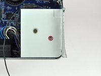
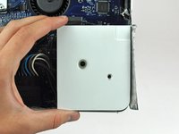
Remove the two Phillips screws securing the access door to the bottom grille of your iMac.
-
-
-
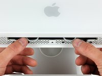
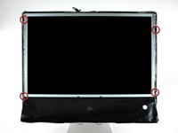
Remove the three T8 Torx screws securing the front bezel to the rear case along the lower edge of the iMac.
-
-
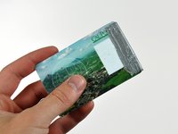
Gereedschap gebruikt in deze stap:Plastic Cards$2.99
-
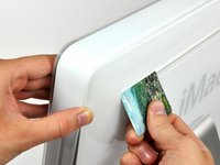
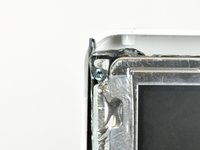
Insert a plastic card up into the corner of the air vent slot near the top of the rear case.
-
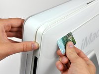
Push the card toward the top of the iMac to release the front bezel latch.
-
Pull the front bezel away from the rear case.
-
Repeat this process for the other side of the front bezel.
-
If the bezel refuses to release, try pressing the lower edge back onto the rear case and repeat this opening process.
-
-
-
Peel the lower EMI shield off the lower edge of the iMac and off the two vertical 4" sections on either side of the iMac.
-
-
-
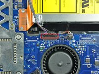
Remove the two T6 Torx screws securing the display data cable connector to the logic board.
-
-
-
-
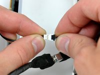
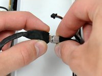
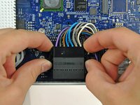
Disconnect the IR board cable by pulling its connector away from the socket on the IR board.
-
-
-
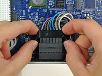
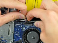
Rotate the top of the logic board toward yourself slightly.
-
Pull the right edge of the logic board toward yourself slightly to free the I/O ports from the rear case, being careful not to bend the board.
-
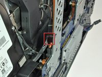
Continue rotating the board toward yourself until you have enough room to reach the SATA connector, shown in the next step.
-
-
-
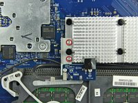
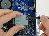
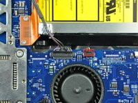
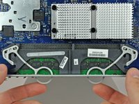
Continue rotating the board toward yourself until you have enough room to reach the SATA connector (shown in red).
-
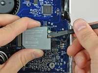
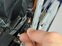
Insert the blunt end of a metal spudger between the SATA connector and its socket. Twist the shaft of the metal spudger to separate the connector from its socket.
-
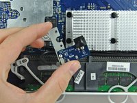
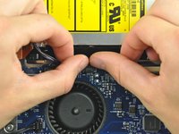
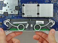
Disconnect the SATA cable from the logic board.
-
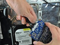
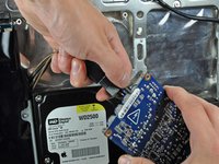
Lift the logic board out of the rear case by its edges, minding any cables that may get caught.
-


To reassemble your device, follow these instructions in reverse order.
To reassemble your device, follow these instructions in reverse order.
Annuleren: ik heb deze handleiding niet afgemaakt.
40 andere personen hebben deze handleiding voltooid.

5 opmerkingen
The images on this stage show the heat shield, cpu and associated pipework as removed but these steps are not included in the inbstructions
Sorry about that, the guide should be fixed now.
Step 40 Sorry, I didn't notice that someone had already commented. The fine threaded (orange) and course threaded (red) screws at the bottom of the machine are reversed. Just need to switch the circles on these two. Anybody know how to work with the images for the manual?