Deze vertaling geeft mogelijk niet de meest recente updates van de bronhandleiding weer. Help ons met het updaten van de vertaling of bekijk de bronhandleiding.
Inleiding
Wanneer de motor niet werkt, of alleen op VOLLEDIG vermogen, is de triac opgeblazen.
Wat je nodig hebt
-
-
-
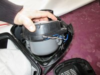
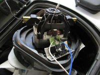
Trek eerst de stekker eruit en rol de kabel op. Koppel de zuigslang los. Open de machine.
-
Er zijn vier PH2-schroeven.
-
Deze schroeven hebben allemaal dezelfde lengte.
 Vraag FixBot
-
-
-
Detail van schroef:
-
Trek eraf.
-
Er is een clip, aan de andere kant is een tweede clip.
-
-
-
Kijk, daar is de tweede clip van STAP 2
-
TREKKEN.
-
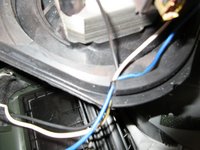
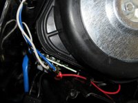
Open. Kijk, de witte kabel en de blauwe kabel moet je verwijderen.
-
De blauwe kabel en witte kabel hebben VERSCHILLENDE MAAT VAN STEKKERS.
-
-
-
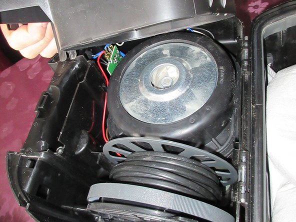
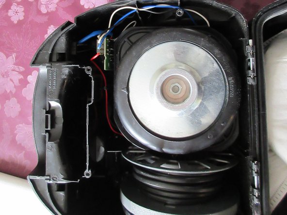
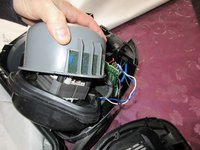
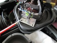
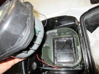
TREK aan de motor, deze heeft een vastzittende rubberen behuizing. Gewoon TREKKEN.
-
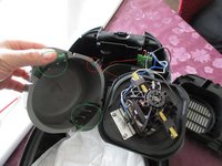
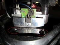
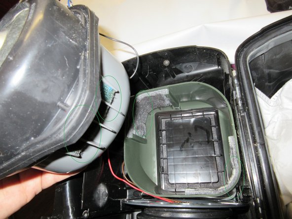
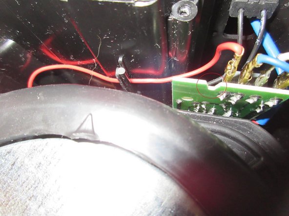
Trek dan aan het grijze plastic gedeelte. Kijk naar de filters, ze moeten tegenover elkaar staan als je ze weer in elkaar zet !!! Gemarkeerd in GROENE cirkels
-
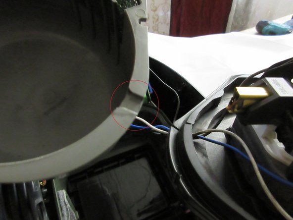
Kijk naar rode cirkel, daar zit een inkeping, daar gaan de Witte kabel, de blauwe kabel en de zwarte kabel door de behuizing.
-
-
-
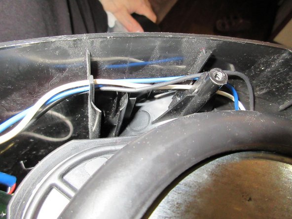
Detail van witte kabel en blauwe kabel. De pluggen hebben een kleine veerhouder, je moet duwen en dan eraf trekken!!
-
De pluggen hebben verschillende maten.
-
Koppel de korte zwarte kabel bij de motor los. De stekker heeft weer een veer die moet worden ingedrukt, trek dan de zwarte kabel eraf
-
-
-
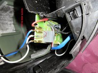
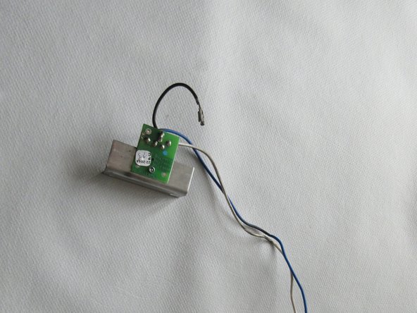
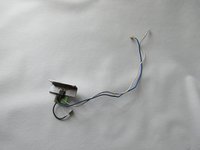
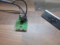
Daar heb je hem. De verbrande TRIAC met kabels en aluminium koeling.
-
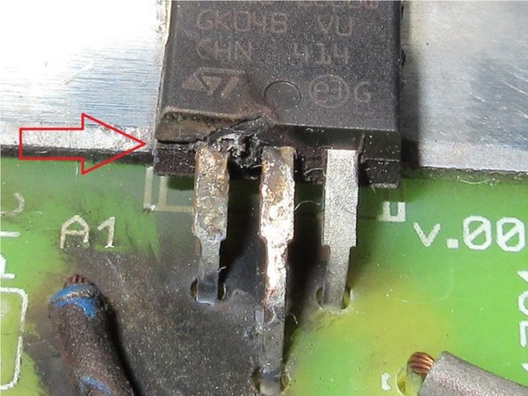
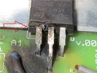
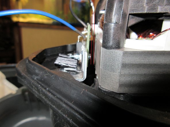
Deze brak bij de behuizing, kijk naar de rode pijl. De pinnen zijn direct bij de behuizing gebogen, dus deze vernietiging vond plaats bij de montage van de triac! ( De stroom liet het exploderen en beschadigde het compleet.
-
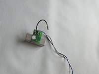
kabels zien er goed uit, printplaat is oké. Het ziet er verbrand uit, maar dit is slechts zwarte aanslag van de rook.
-
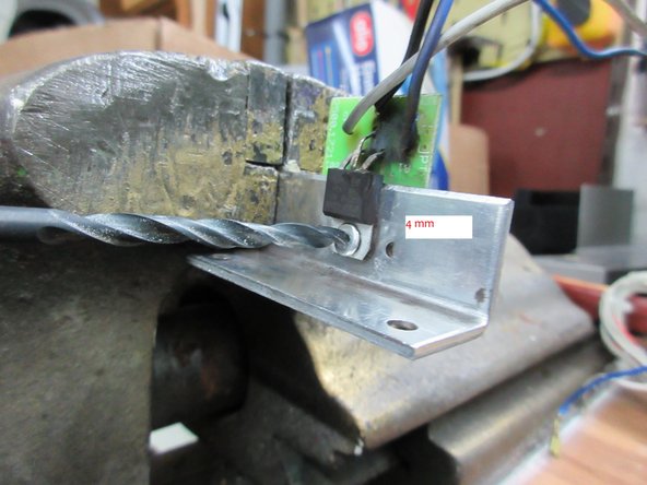
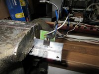
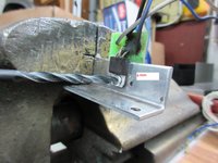
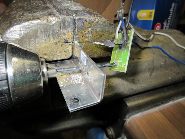
Nu moeten we dat deel uitboren...
-
-
-
-
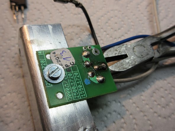
trek dan de defecte TRIAC omhoog.
-
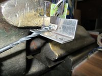
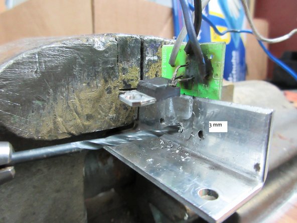
dan boor je met 3 mm om door de printplaat te boren.
-
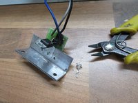
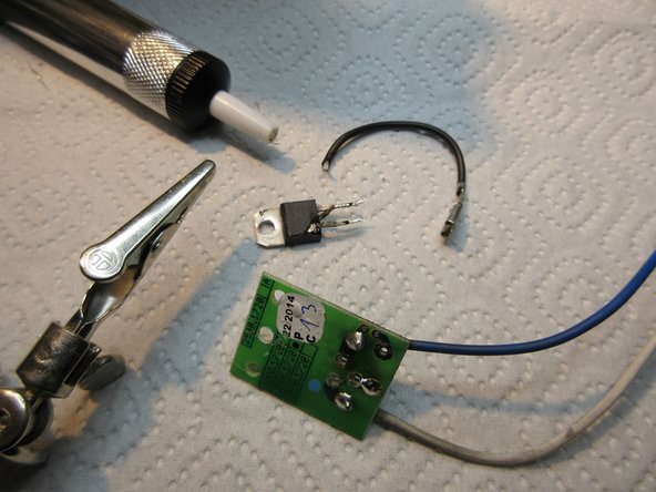
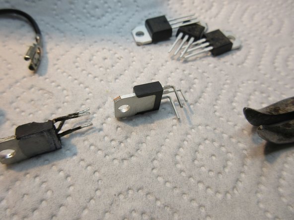
daar heb je het, alle delen gescheiden. :)
-
-
-
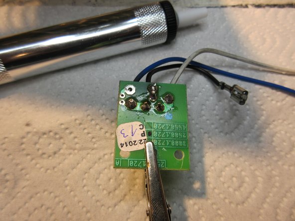
desoldeer het nu. De printplaat heeft twee gaatjes die op de aluminium koeler passen.
-
Geen probleem met tinzuiger.
-
-
-
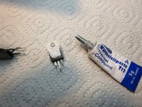
neem wat thermische pasta. Slechts een heel klein beetje.
-
neem M3-schroef, M3-ring en monteer deze op het aluminium gedeelte.
-
soldeer het nieuwe onderdeel na de mechanische montage.
-
-
-
ik heb een koelingsupgrade gemaakt, je hoeft dit ook niet te doen omdat dit een doe-het-zelf-aanpassing is die niet echt nodig is. XD
-
-
-
NU OPNIEUW MONTEREN
-
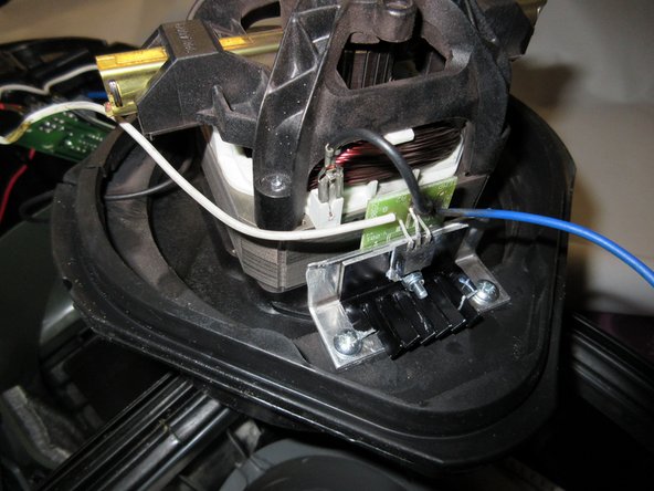
zet hem terug, dan heb je de twee KORTE ph2 schroeven nodig.
-
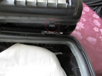
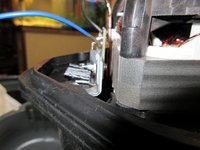
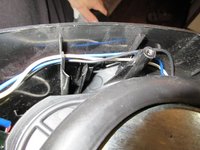
Let op de afstand tussen de onderdelen zoals op de derde foto, deze heb ik gemarkeerd met twee rode lijnen.
-
-
-
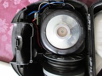
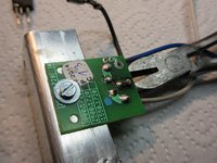
plaats dan de witte en de blauwe kabel, er is ook een tweede lange zwarte kabel.
-
Kijk naar de inkeping, die moet goed passen.
-
zorg daar voor de juiste pasvorm van de filters.
-
-
-
Detail van de kabels.
-
Er zijn inkepingen om de kabels vast te houden.
-
Kijk, er zit een grote inkeping in de printplaat van de derde foto. RODE CIRKEL. In deze inkeping grijpt een grendel van de behuizing wanneer je dat onderdeel sluit. Kijk bij stap 1 t/m 4 om te zien waar u voor vergrendelingen en inkepingen en clips moet zorgen.
-
-
-
Pas als alle onderdelen gelijk in elkaar passen, alle grendels en inkepingen en clips in elkaar passen en je de behuizing stevig naar beneden duwt, kun je voorzichtig de 4 langere schroeven indraaien
-
Testen, functioneren, klaar, nu een Jägermeister.
-
-


Voer de stappen in omgekeerde volgorde uit om uw apparaat weer in elkaar te zetten.
Annuleren: ik heb deze handleiding niet afgemaakt.
4 andere personen hebben deze handleiding voltooid.
Met dank aan deze vertalers:
95%

Toon Konings helpt ons de wereld te repareren! Doe je mee?
Begin met vertalen ›

5Gids Commentaar
Well, my child played with that Vacuum-cleaner and it overheated.
So I had to do this repairmanual for you.
Do not let play children with Machines. ;)
Just some comments for English speakers. I'm not dealing with spelling or awkward phrasing - I think it's clear emough. But for those that aren't sure on certain words, maybe this will help.
First tool listed is a #2 Philips-head screwdriver. So when you see PH2 screws, use your phillips screwdriver (also known as a cross screwdriver in some parts of the English-speaking world).
Step 2, middle bullet - "Pull, it knacks" literally would be cracks, which might sound negative. So "Pull, it does separate."
Step 4 (and elsewhere): turbine or motor.
Step 6, 1st bullet (& see Step 9 and elsewhere for variations) - (aluminium-)cooling or cooler = (aluminum) heat sink. [Americans don't use the 2nd i of aluminium.]
Step 6 (and elsewhere), 3rd bullet: platine = printed circuit board (I'll always refer to it as the PCB).
Part 2 of notes comes in my next comment --
Part 2 of notes here --
Step 6, 2nd bullet [I know, out of order, but I wanted to use PCB, so translated it first] - Instead of translating it "The pins are bent directly at the housing, so this destruction occured at the montage of the triac !" I would've said "The pins are bent to go into the PCB, and the destructive forces inside the triac caused the assembly ("montage") to burst open at the other end of the pins, where they enter the triac housing!"
Steps 7-8 - there is a rivet that goes through the triack, then through the heat sink, then through the PCB. For getting the rivet out, you drill with a 4mm drill bit through the rivet head, through the triac mount, and lift the triac out of the way, then continue very carefully through the heat sink. Now the PCB can be removed from the heat sink. Then switch to a 3mm bit and drill the remnants of the rivet out of the PCB.
Part 3 coming up --
Part 3 of 3 here
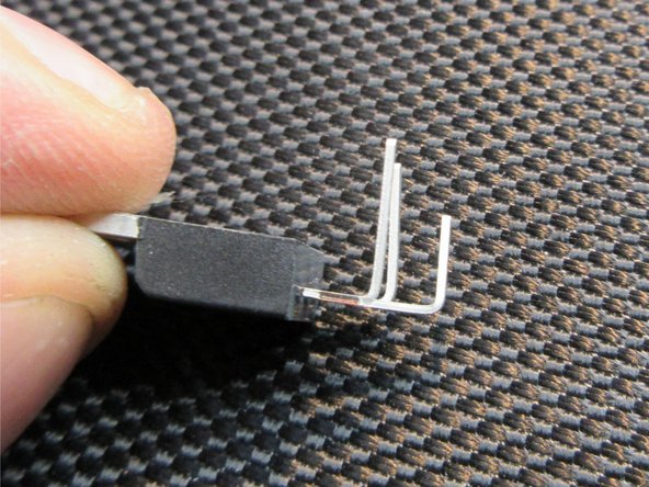
Step 10 - "follow the steps like on the pictures, i can't explain it, sorry. Like on the pictures, you can see, do it too" becomes "Follow the pictures in steps 4-10, especially step 6 and step 10. Pins 1 and 3 get bent closer to the triac, pin 2 (the middle pin) gets bent further out ('longer') from the triac, to fit the wholes in the PCB.
Step 11, 1st bullet - use less thermal grease/compund than is shown in the picture of step 11. He said "little" and that was correct.
Step 11, 2nd bullet - Instead of riveting (if you aren't good at it you might break the PCB), he replaces it with a bolt, washer, and nut. Tighten it - but not so much you break the PCB.
Starting Step 13, you're reassembling. His CONCLUSION at the end says to do the steps in reverse order to finish - maybe he later added steps 13 to the end later and didn't remove that statement.
Step 17 Jägermeister = hunt master -- go hunting things to vacuum up?