Inleiding
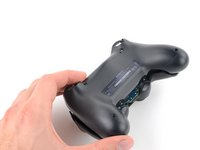
Follow this guide to replace the button circuit membrane in your DualShock 4 model CUH-ZCT1U controller.
Wat je nodig hebt
-
-
Check the model number on the back of your controller. This guide was written using model CUH-ZCT1U. If you have another model, the guide procedure and replacement parts may differ slightly.
-
-
Gereedschap gebruikt in deze stap:Microfiber Cleaning Cloths$3.99
-
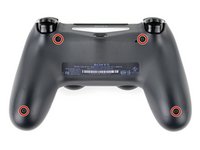
Use a Phillips screwdriver to remove the four 6.4 mm-long screws securing the rear case.
to re-torque these PH00 screw... i found 19Ncm to be about the max. (since 27Ncm was too much)
-
-
-
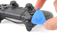
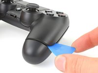
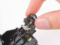
Use an opening pick to pry each corner of the L1 button from the front case.
-
Remove the button.
-
-
-
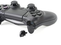
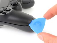
Use your opening pick to pry and remove the R1 button, just as you did for the L1 button.
-
-
-
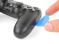
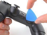
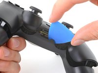
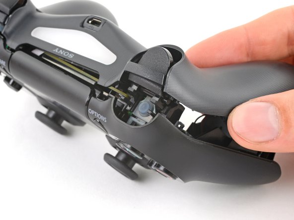
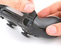
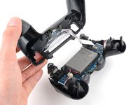
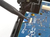
Insert your opening pick at a downward angle between the front case and rear case, halfway between the handle and the action buttons.
-
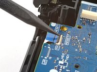
Slide your pick toward the handle and pry up to release the first clip.
-
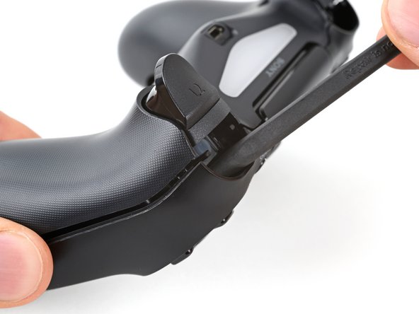
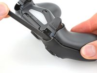
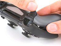
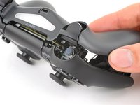
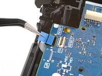
Repeat this procedure on the other side of the controller to release the second clip.
-
-
-
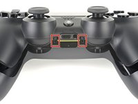
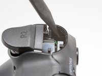
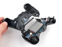
Locate the clips by looking through the gap above the R2 or L2 buttons.
Ah, well perhaps I may have broken a tab by not removing the buttons but if be more worried about breaking the buttons
-
-
-
Gereedschap gebruikt in deze stap:Tweezers$4.99
-
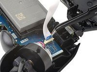
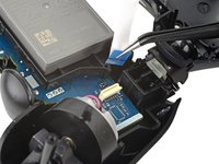
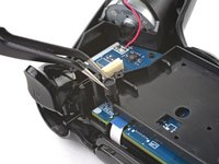
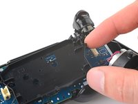
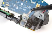
Use tweezers or your fingers to remove the interconnect cable by pulling its blue pull tab straight out of the socket.
On the model CUH-ZCT2E the circuit board is mirrored so that the connection is on the left side. When reassembling the blue tab should be facing inwards.
I just left the interconnect cable attached and held things out of the way when I put in the new battery
-
-
Gereedschap gebruikt in deze stap:Tweezers$4.99
-
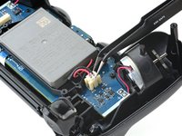
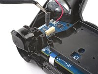
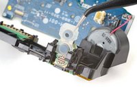
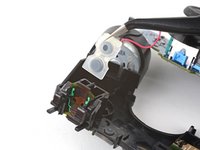
Use tweezers or your fingers to grab and disconnect the head of the battery cable from the motherboard.
-
-
-
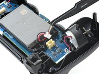
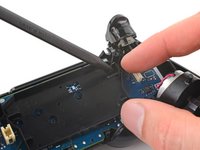
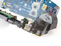
Grab and remove the reset button extension from its recess in the battery bracket.
On the model CUH-ZCT2E this is part of the battery bracket and not removable. Just skip this step.
-
-
-
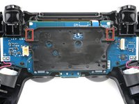
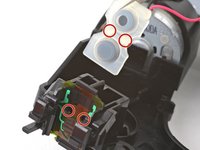
Locate the two clips securing the battery bracket to the motherboard.
-
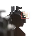
Insert the point of your spudger into the opening behind the right bracket clip.
-
Depress the clip to disengage it from the motherboard.
-
Lift up the right edge of the battery bracket.
On the model CUH-ZCT2E the battery bracket is not secured by clips but by a PH #00 screw mid height on the right half of the battery bracket. Just remove the screw and for the next step lift the battery bracket straight up.
-
-
Gereedschap gebruikt in deze stap:Tweezers$4.99
-
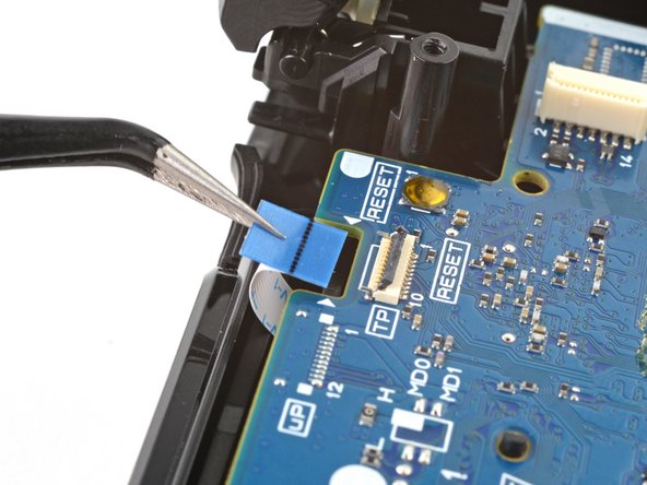
Use the point of your spudger to flip up the locking flap securing the touch pad cable ZIF connector.
-
Use tweezers or your fingers to disconnect the cable using its blue pull tab.
-
-
-
Use your Phillips screwdriver to remove the 6.4 mm screw securing the motherboard.
On the model CUH-ZCT2E this screw was removed in step 16. Just skip this step.
-
-
-
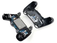
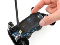
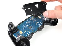
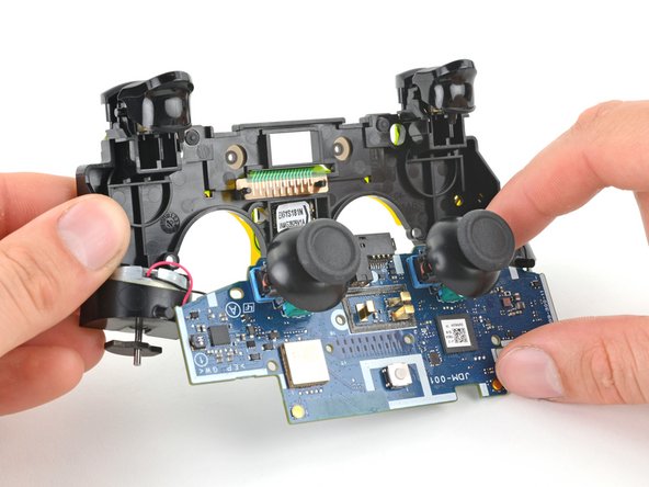
Grab the midframe by its plastic protrusions or the vibration motors and remove it.
-
-
-
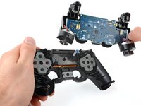
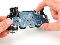
Lift the motherboard and flip it over the bottom of the midframe, leaving the vibration motor cables attached.
-
-
-
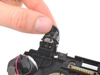
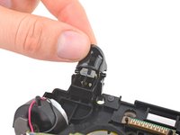
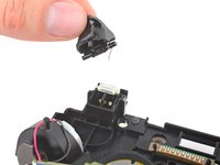
Firmly grip the R2 button and unclip each peg from the midframe.
-
Remove the R2 button.
-
-
-
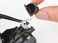
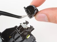
Unclip the L2 button from the midframe and remove it, making sure not to lose the small spring from the inside peg.
-
-
-
Lay the midframe face-down and orient the button properly.
-
Place the spring over the inside peg with its bent ends facing upward.
-
Rest one end of the spring in its channel in the button.
-
Place the button over its clips and rest the other end of the spring in its channel in the midframe.
-
Press the button's pegs into their clips until they snap into place.
-
-
-
Grab the upper edge of the R1 and R2 button pad.
-
Slide the pad out of its channel in the midframe.
-
-
Gereedschap gebruikt in deze stap:Tweezers$4.99
-
Use tweezers or the point of a spudger to lift the underside of the R1 and R2 section of the button circuit membrane.
-
Slide the membrane over its retaining tab on the midframe.
-
-
-
Grab each side of the button circuit membrane.
-
Feed the middle section of the membrane through its cutout in the midframe.
-
Remove the membrane.
-


Compare your new replacement part to the original part—you may need to transfer remaining components or remove adhesive backings from the new part before installing.
To reassemble your device, follow these instructions in reverse order.
Take your e-waste to an R2 or e-Stewards certified recycler.
Repair didn’t go as planned? Try some basic troubleshooting, or ask our Answers community for help.
Annuleren: ik heb deze handleiding niet afgemaakt.
14 andere personen hebben deze handleiding voltooid.

Team

9 opmerkingen
I’ve changed two flex boards from two different sellers, and I keep having a battery drain of about 25mA after i installed them. The battery drain is not present with the original flex board, any ideas?
Ok no, little update. the battery drain is present even if I disconnect the flex board, the touch connector and the led . It’s something on the main board I think, but I can’t figure out what is it. Is there some insulation that I may have lost when changing the flex board the first time?
That sounds really weird. I don’t remember any insulation on this specific model of controller. I don’t have this anymore as it was a repair for a friend and I also hadn’t noticed or measured such a drain.
Devnol -
The only other thing I can think of is a failure on one of the components soldered on the main board, but 20mA in standby condition are VERY high!
The warning regarding the rumblers being hard soldered and the wiring is delicate honestly should be in step 4, jiggling joysticks to remove the front cover can easily cause the rumblers to be disconnected and require some time consuming resoldering to reattach them.
Good point! From the fact that I used the word "again" in step 6, I may have had that in at some point but something happened and I accidentally removed it. I'll add it back. Thanks a lot for the feedback!
Devnol -
As of March 14, 2023, this guide has been updated! Comments regarding step procedures may no longer be relevant.
Buenos días. En mi caso cambie el flex, cambie las gomitas conductoras y así y todo sigue sin funcionar el R2. Sabrán cuál es el problema???
Hi! I'm sorry your R2 button doesn't work. You have some options. 1) Look for damage on the silicone button pad. Make sure the R2 button can push the pad onto the button circuit membrane. Look for damage that prevents the button from pressing. 2) Clean the silicone pad where it touches the button circuit membrane. Dirt or dust might block the connection. 3) Follow the connection on the button circuit membrane to where it connects to the motherboard. Clean the contact on the motherboard and look for electrical damage.
If you have more questions, ask the community!
Good luck!
model:cuh-zct2e
كيف يمكن ان افكها
Mhmod - Antwoord