Deze versie kan foutieve bewerkingen bevatten. Schakel over naar de recentste gecontroleerde momentopname.
Wat je nodig hebt
-
Deze stap is niet vertaald. Help het te vertalen
-
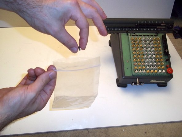
Prepare your workspace. Cover it with clean white paper or a white mat board. Light the area more than you think you'll need, and preferably from multiple directions.
-
Ready a cardboard box and lots of press-to-close bags to store the parts you pull off. Keep associated parts in their own bag, label each bag, and don't skimp on the number of bags!
-
-
Deze stap is niet vertaald. Help het te vertalen
-
Let's first remove the carriage, which is the top part with all the number wheels on them.
-
Position the calculator so that its keyboard faces you. This orientation defines the left and right sides of the calculator.
-
Insert a 1/8" flathead screwdriver into each of the indicated two screwheads on the right and left sides of the carriage, simultaneously.
-
Unscrew the left side screw.
-
-
Deze stap is niet vertaald. Help het te vertalen
-
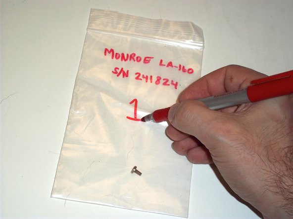
Remove the left side screw.
-
Put it in a bag!
-
You should label each bag with the model number and serial number.
-
You can find the serial number by turning the calculator upside down and peering into the slot cut into the bottom, which gives you the model number and serial number.
-
Label the bag 1 so that you know where in the sequence this part was pulled off.
-
-
Deze stap is niet vertaald. Help het te vertalen
-
Put the bag in a box labeled with the model and serial number.
-
Pat yourself on the back. You are now officially organized.
-
-
Deze stap is niet vertaald. Help het te vertalen
-
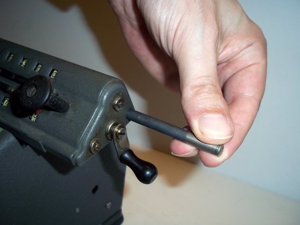
Get something pointy, like a small screwdriver, and push it into the hole on the left side of the carriage that was revealed by the screw being removed.
-
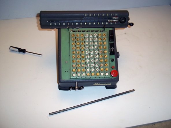
This will push out the carriage shaft from the right side. Grab it and pull it out all the way.
-
Put the carriage shaft in your box of parts.
-
-
Deze stap is niet vertaald. Help het te vertalen
-
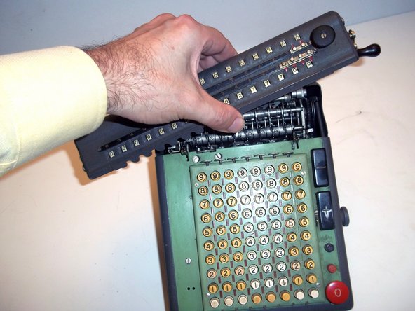
Pull back on the two carriage latches.
-
With the other hand, lift the carriage up and away.
-
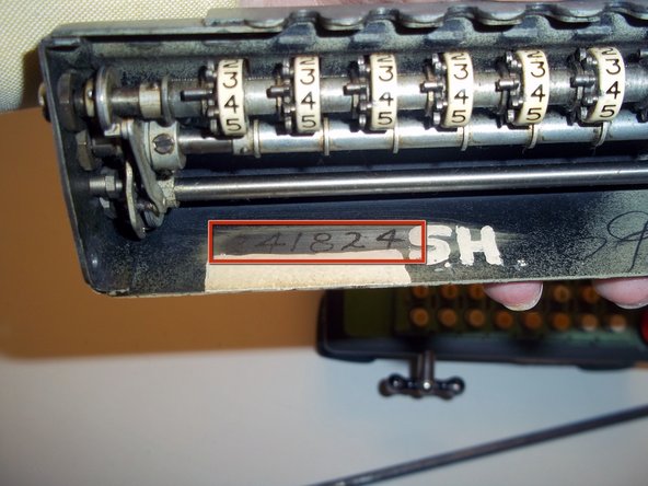
On the underside of the carriage is inscribed the serial number of the machine, in case you couldn't read it from the slot in the underside.
-
Mine is serial number 241824. Also, apparently Stapler Guy was really possessive of this calculator.
-
-
Deze stap is niet vertaald. Help het te vertalen
-
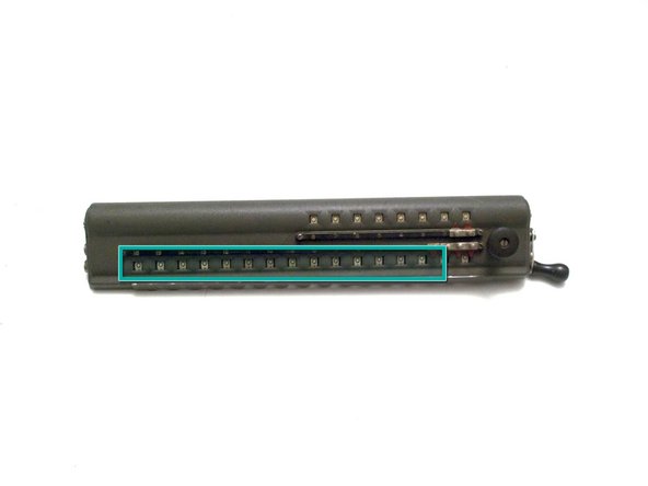
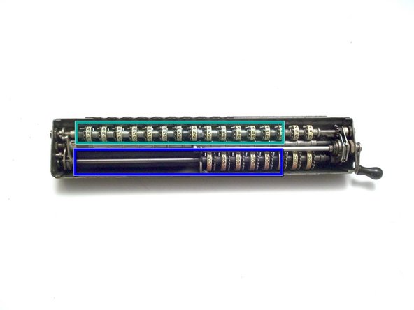
Upper Dials. Consists of eight individual dials with black and red digits. Shows the multiplier in multiplication, and the result of division.
-
Lower Dials. Consists of sixteen individual dials, showing the result of addition and multiplication, the remainder in subtraction, and the dividend in division.
-
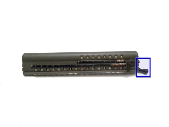
Dials Clear-out Crank. Rotate forwards one turn, stopping at bottom, to clear out upper dials. Backwards for lower dials.
-
-
Deze stap is niet vertaald. Help het te vertalen
-
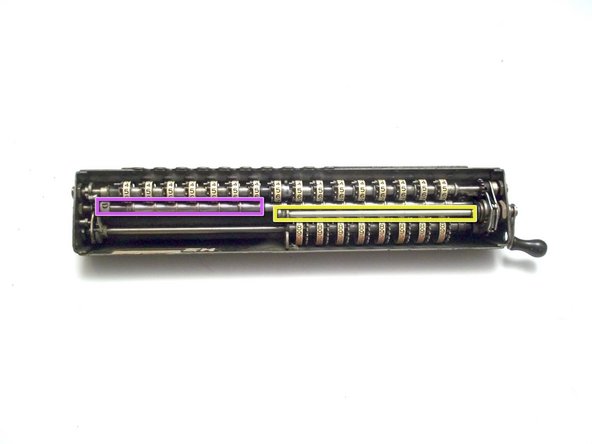
Clutch mechanism. Drives either the lower shaft or upper shaft, but not both.
-
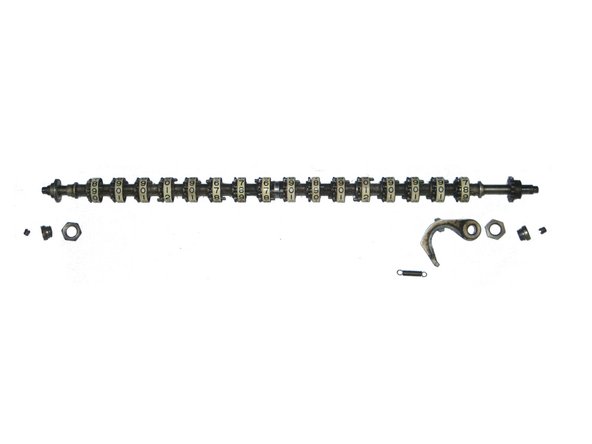
Lower Dials shaft and wheels.
-
Upper Dials shaft and wheels.
-
Zeroing shaft.
-
Carriage lifting shaft, only active when zeroing the Lower Dials.
-
-
-
Deze stap is niet vertaald. Help het te vertalen
-
Nelson White's U.S. patent "Zero-setting mechanism", filed in 1920, describes how this amazing thing works.
-
The clutch rotates one gear forwards when the crank is turned forwards, and it rotates another gear backwards when the crank is turned backwards.
-
One gear turns the upper shaft, the other gear turns the lower shaft. Little arms on the clutch lock the shafts into place when they are not turning.
-
On the left side of the carriage, cams on the upper and lower dials move a lever on the central zeroing shaft. Fingers on the zeroing shaft as a result move into place so that when the upper or lower shaft is rotated, the wheels stop when they display zero.
-
The zeroing mechanism rarely completely fails. It is useful to rotate the crank while observing all the different parts to gain an understanding of each part's function.
-
-
Deze stap is niet vertaald. Help het te vertalen
-
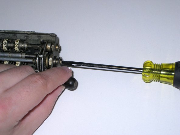
Turn the carriage to the right side.
-
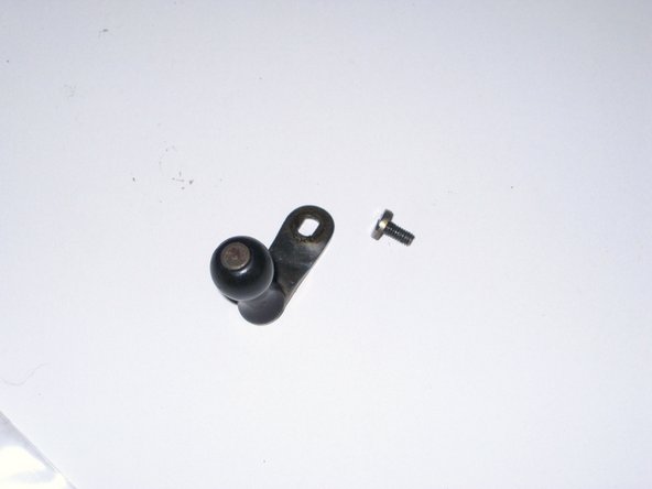
Holding on to the crank, remove this screw.
-
Put the crank and screw in bag #1.
-
-
Deze stap is niet vertaald. Help het te vertalen
-
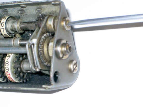
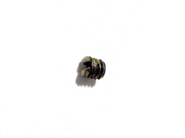
Remove this set screw.
-
Set screw: 5-44 x 1/8"
-
Put the set screw in bag #1.
-
-
Deze stap is niet vertaald. Help het te vertalen
-
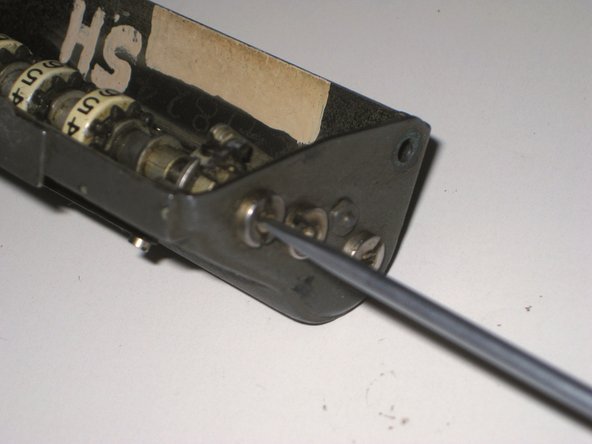
Turn the carriage to the left side.
-
Remove this set screw.
-
Set screw: 5-44 x 1/8"
-
Place the set screw in bag #1.
-
The set screws are used to align the shaft along its axis.
-
-
Deze stap is niet vertaald. Help het te vertalen
-
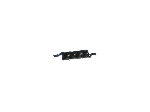
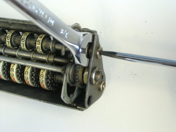
This spring on the right side of the carriage needs to be removed.
-
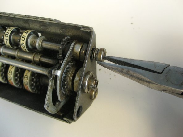
Pull the arm on the right upwards to get better access to the spring.
-
-
Deze stap is niet vertaald. Help het te vertalen
-
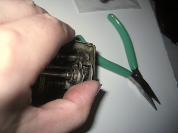
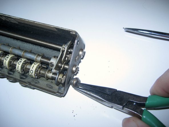
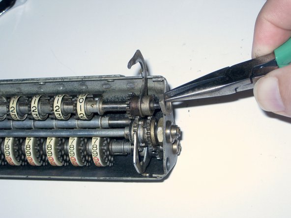
With the arm raised, use needlenose pliers to pull the spring off the arms.
-
Spring: Expansion, 0.31" compressed x 0.11", wire 0.014"
-
Place the spring in bag #1.
-
-
Deze stap is niet vertaald. Help het te vertalen
-
Spread the arms out.
-
Use a 3/8" wrench to hold the nut, and unscrew the bushing.
-
Remove the bushing, and put it in bag #1.
-
The nut stays in for now.
-
-
Deze stap is niet vertaald. Help het te vertalen
-
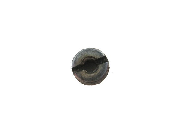
A close-up of the bushing.
-
It is hollow and threaded on the outside, 1/4-32 x 1/8", and the head is threaded on the inside for the set screw.
-
Its head is 0.296" x 3/16"
-
-
Deze stap is niet vertaald. Help het te vertalen
-
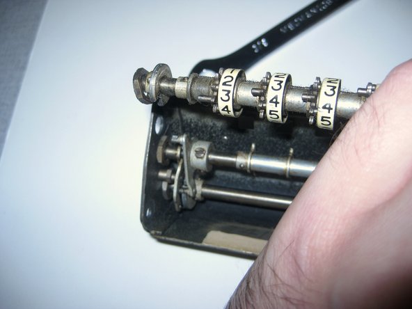
On the right side, lift up the Lower Dials shaft by the arm.
-
You can now get to the nut. Remove it and put it in bag #1.
-
-
Deze stap is niet vertaald. Help het te vertalen
-
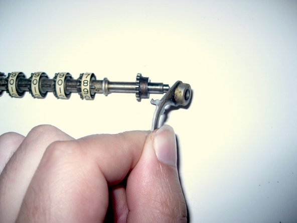
Still lifting on the right side of the shaft, turn the shaft so that the cam on the left side engages the pin.
-
Now lift up on the left side of the shaft to free it.
-
The left side nut may fall off, or not. If it tries to escape, make sure you see where it went.
-
-
Deze stap is niet vertaald. Help het te vertalen
-
Remove the nut from the left side of the shaft, or the floor, or wherever it ended up, and place it in bag #1.
-
Remove the Lower Dials shaft arm from the right side of the shaft, and place it in bag #1.
-
-
Deze stap is niet vertaald. Help het te vertalen
-
The parts of the Lower Dials are fixed to the shaft using tapered pins.
-
During installation, the part is placed on the shaft, held in place, and then a hole is drilled through the part and the shaft using a taper pin drill bit.
-
Next, a taper pin is inserted into the hole until it stops, then it is pressed in with an arbor press. The pin is then cut or ground off.
-
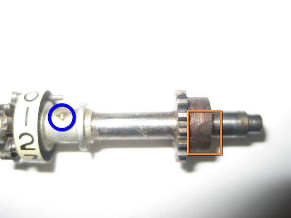
Indicated is a hole in the Lower Dials driver gear for its taper pin.
-
In this dial spacer, the taper pin is clearly visible.
-
Rotating the shaft to the other side, we can see the over-enthusiastic application of a grinding head applied to the other end of the taper pin on the driver gear.
-
Meanwhile, the taper pin is again clearly visible on the dial spacer.
-
-
Deze stap is niet vertaald. Help het te vertalen
-
Removal of taper pins requires an arbor press and pin punches, and preferably a pin punch holder.
-
For this disassembly, you will need 1.1 mm or 1.0 mm pin punches, and you will need a lot of them, maybe ten or twenty, since they will often break.
-
Before you use a pin punch, cut it down to 1/4" or so using a Dremel or some other cut-off tool.
-


Annuleren: ik heb deze handleiding niet afgemaakt.
4 andere personen hebben deze handleiding voltooid.

2 opmerkingen
Thanks for posting this. My LA-200X is not zeroing out one wheel when on 1(black). This will help me tackle the repair.