
Canon EOS Rebel T7i Top Cover Replacement

Inleiding
Ga naar stap 1This guide shows you how to replace the top cover of the camera. This is also useful if you are trying to repair or replace a particular part located on the top cover, or are trying to gain access to a different component further inside the camera.
Note that the Phillips #000 screwdriver is marked as an optional tool as you can always use the JIS #000 screwdriver in its place (JIS screwdrivers won't damage Phillips head screws).


-
-
Before beginning, remove the battery and SD card from the camera.
-
Using your thumbs, push up on the eyepiece to remove it.
-
Remove the battery door.
-
Open the battery door to about a 35° angle.
-
Pull the battery door straight outwards.
-
-
-
Underneath the right I/F terminal cap, remove the following screws:
-
Two M1.7x5.5mm JIS #000 screws
-
On the right side of the camera, remove the following screws:
-
Two M1.7x4.5mm JIS #000 screws
-
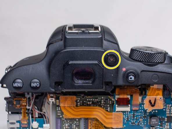
On the back of the camera, remove the following screws next to the viewfinder:
-
Two M1.7x5.0mm Phillips #000 screws
-
-
-
On the bottom of the camera, remove the following screws:
-
Four M1.7x5.0mm Phillips #000 screws
-
Using a plastic opening pick, partially peel up the top of the back rubber grip.
-
Carefully begin lifting the back cover up away from the camera body.
-
Using a plastic spudger tool, gently pry off the back cover ribbon cable from the main PCB board.
-
-
-
-
Underneath the left I/F terminal cap, remove the following screw:
-
M1.7x5.5mm JIS #000 screw
-
Using a plastic opening pick, peel off the front name plate.
-
Underneath where the name plate was, remove the following screw:
-
One M1.7x5.5mm Phillips #000 screw
-
Pull off the I/F terminal cover.
-
-
-
Remove these two cables from the main PCB board using a plastic spudger tool.
-
Remove the third cable using a pair of blunt tweezers.
-
Place the end of the tweezers in the small notch in the cable connector and push the connector out.
-
Using a pair of blunt tweezers, carefully pull out the red and yellow cables from the DC PCB board.
-


To reassemble your device, follow these instructions in reverse order.
To reassemble your device, follow these instructions in reverse order.
Bijgevoegde documenten

Team
