
No Picture. Backlight and Sound Work
Hisence 65U6G
I have ordered all of the boards in a kit from shopjimmy however while swapping left and right T-Con output cables I noticed one had a burned trace. I flipped the cable end for end and it burned another trace on the same connector PIN number.
I have now also ordered new 60 pin cables.
My concern is I can not determine if the problem is with the panel, T-Con, or something upstream of the T-Con board.
Maybe someone can help with a schematic? The T-Con part number is 290410.
I really hate firing the parts cannon without a clear target.
Thanks,
Bill


Is dit een goede vraag?
Score
1

15 opmerkingen
@bbmc don't connect your display but can you measure the VDC on VGH AND VDDA. Test Points are be just center right on your right connector. Voltmeter set to DC at about a 50V range Black to ground and Red to testpoint. Do the same with VCOM on the other connector side
door oldturkey03
[image|2759791][image|2759790]
Thanks for the quick reply.
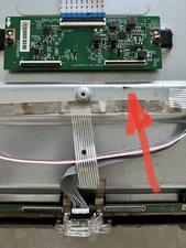
When I removed the shorted cable from the right output of the T-Con board I got a picture on the left side of the display.
You can see at the tip of the red arrow burn marks on the chassis. I do not see any physical damage to any of the boards popped caps, blown smds, etc. I'm flying blind without a schematic.
My hope is that the problem is upstream of the panel. If so I should be good firing the parts cannon. Worst case I'm out $125 in cannon fodder.
door BBM2C
@oldturkey03
Thanks again!
I measured 19.40 VDC at both test points.
EDIT: and 8.21 VDC at VCOM
door BBM2C
Ok that is the voltage to the Panel and the common to the board. Nothing spectacular. Darn, I hope it's the cable/board. The driver boards on the panel look okay? Anything scorched etc. that you can see? Careful you don't pull the ribbon cables off the LCD panel.
Did the Kit have the T-con board with it? You still have the old one?
door oldturkey03
@oldturkey03
The kit includes every board. Power, Main, Driver, T-Con, and WiFi plus I ordered two new cables that connect T-Con to panel.
As I noted above I do not see any damage to any of the boards.
(Edit: There is some surface rust on the RG6 connector shield).
I did notice the 18 volt rail on the PS board to main board measured 16.6 vdc.
I'll add hi-rez pics of the boards to the original post.
Thanks,
-BB
door BBM2C
10 commentaren meer tonen