Ga door naar hoofdinhoud

Handleidingen voor reparatie en demontage voor koelapparaten van levensmiddelen, waaronder koelkasten, diepvriezers en koel-vriescombinaties.

1649 Vragen Bekijk alle

Waeco cf 40 car fridge

Waeco cf 40 car fridge

runs on 240v but not on 12v

Fuse ok

did find on mother board the negative wire leading to fridge light has a 12v current

as does the positive

power is getting to the display but nothing lights up

it does on 240v so display is

Block Image

The 7 pins all get 12v there’s no earth return from the circuit board which gets powered from the battery

Block Image

the connection on the bottom right is from the compressor control panel

3rd from the bottom left is the power for the fridge light one is positive the other pin should be negative but it gets 12v

I’m wondering if this is why the control temperature panel will not power up on 12v and neither will the fridge compressor

all ok on 240v

Beantwoord! Bekijk het antwoord Dit probleem heb ik ook

Is dit een goede vraag?

Score 0
15 opmerkingen

Hi @golde ,

Unusual that the -ve leg has 12Von it as the power supply from a car etc is +12V and usually the components in a DC system are fed +12V and the -ve side is earth or -12V with respect to the +ve side of the supply. Is this what you perhaps measured?

Maybe start at where the DC power is connected to and make sure that there is +12V DC when measuring between the +ve and the -ve on the DC input to the fridge. After that you will need to make sure that the +ve supply is going to where it should.

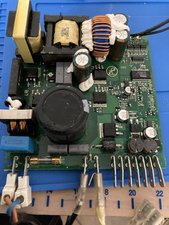
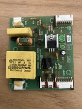
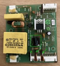
Post some close up images on the circuit board (both sides) back here perhaps something will be seen.

Here's how to do this. Voeg afbeeldingen toe aan een bestaande vraag

door

Ok thank you I’ll check it out

door

If I put the negative lead from the multi meter on the negative pin I get a 12v positive reading on all 7 pins on the compressor board


then if I run the continuity test or diode mode I get a reading from those 7 pins


Then if I put one lead from the multi meter pin 3 and the other on pin  5 which are the common those pair give me continuity so those 2 are joined


now I’m assuming that with the red lead from the multi meter and place that on the postive feed pin from the battery and the black lead from the multi meter on either pin 3 or 5 I should get a positive 12v reading

however this postive 12v reading only happens when I put the black lead on the negative feed pin from the battery and put the red lead from the multi meter on either pin 3 or 5 which I thought supposedly common or earth pins


door

The 3 black wires that go from

the control board to the compressor all give a 12v reading

However the compressor won’t run and neither will the circuit board for the temperature control

On 240v all works fine

door

I double checked postive and negative are on the correct pins

door

10 commentaren meer tonen

Voeg een opmerking toe

1 Antwoord

Gekozen oplossing

Hi @golde ,

I don’t know if a CF40 is the same as a CF80 but it uses the same main control board .

According to this link here is the pinout for the 7 terminals for the DC input on the COMP board

COMP pins

1 +BAT +12 or 24 V DC

2 A (lamp) +12V DC

3 C (common)

4 D (alarm)

5 C (common)

6 P (protection)

7 T (thermostat)

Usually Common means earth or -ve battery as verified in the link “Common” is effectively –BAT or battery negative.

If you connect the voltmeter between pin 1 (red meter lead) and pin 3 (black meter lead) there should be 12V DC. If you read -12V DC on the meter either the meter leads are reversed or the DC power supply to the unit is reversed.

The link also has the wiring diagram for a CF80 but you have to register with the website to access it.

Also I would check what has happened to the capacitor in the image shown below as it looked liked it leaked or something got hot near it, also the marks on the board as shown arrowed, don’t look right (heat?). Check the other side of the board for good solder connections etc.

Block Image

Hopefully this is of some help.

Was dit antwoord nuttig?

Score 0

9 opmerkingen:

Thankyou so much I’ll check it out

door

Thanks again for the reply

Unfortunately the capacitor isn’t the problem I unsoldered it and it tested ok

I think the brown stuff is some sort of glue

All the 12v power is coming from the other board from all the 7 pins

door

@golde

Just verifying that there is 12V on every pin of the COMP connector on the board shown in the image above?

What happens if you disconnect the cable from the COMP connector and use an Ohmmeter to measure between all the pins from +ve thru to T? Are there short circuits between one pin to the next?

They are all individual leads so you wouldn't expect them to all have +12V on them especially the common lead as it should be -ve batt

door

Hi @golde ,

You may have to check that the +ve lead from the battery actually goes to the +ve pin on the board by disconnecting the cable connected to the board and measuring on the cable itself.

Place the meter's black lead on the battery's -ve terminal and then probe with the red lead on the +ve wire in the cable plug. It should show +12V

door

Hi @golde ,

You may have to trace the +ve track from the COMP connector and see where it goes to.

I think that it goes to the +ve pin on the CP4 connector but it must also go somewhere else.

Also you said that there was continuity between all the 7 pins on the COMP connector. Was this with the COMP cable disconnected?

This doesn't sound right. You may have to literally draw the circuit diagram to find out what goes where and how it all ties together,i.e. trace from each pin to see which component(s) it goes to etc.

Fault finding without a schematic is tedious. You can test the main components to see if they are reasonably OK i.e. not open circuit or short circuit e.g. U4, D1 U5 etc. Also did you check on the other side of the board where the "burn" marks appear to be to see it anything is obvious there or where they connect to? It got hot for a reason and usually burn marks are caused by excess current flow.

door

4 commentaren meer tonen

Voeg een opmerking toe

Voeg je antwoord toe

Gerry Golden zal eeuwig dankbaar zijn.
Weergavestatistieken:

Afgelopen 24 uren: 2

Afgelopen 7 dagen: 7

Afgelopen 30 dagen: 60

Altijd: 3,406