Ga door naar hoofdinhoud

Repair information and guides for the iPhone 6 that was released on September 19, 2014. Model Numbers: A1549, A1586, and A1589

4994 Vragen Bekijk alle

iPhone 6 U2 ic Replacement

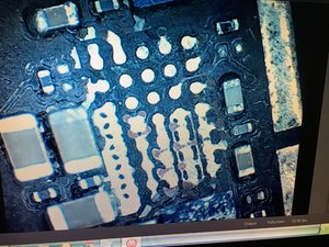
I have an iphone 6 that dropped in water, i cleaned the motherboard and it worked fine for a month. Then it started reboot sometimes and flashing on apple logo. I tried to restore and returns error 9. I search at google and i decide to change the U2 ic. I removed the old U2 ic chip and by fault i removed the two capacitors near this chip. Please see the photo below...

Block Image

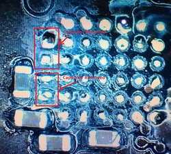
Can someone help me, is this two capacitors so important and i need to find others to replace or just let it like this and solder the new U2 ic?

I would appreciate your help. thank you!!!

Beantwoord! Bekijk het antwoord Dit probleem heb ik ook

Is dit een goede vraag?

Score 2
Voeg een opmerking toe

2 Antwoorden

Gekozen oplossing

The one at the bottom of the image is C1754 (0.1MF/4V/01005) and the top one is C1739 (0.01MF/6.3V/01005).

Are they necessary? You should be able to test your repair without them but if you are charging a customer for this repair, then you should replace them. Engineers put them there for a reason. They are easy to source (Digi-Key) and inexpensive.

These capacitors are used to filter the power rails from any "noise" on the line and they are put as close to the IC as possible. Considering that the Tristar IC is used for communications, I would say it is important to have them there.

If you are doing micro-soldering repairs, you really should have schematics and boardviews? There are free versions on the web or you could license ZXW Tools for less than 100$.

As an aside, you ask lots of questions and many repair techs invest time to give you thoughtful answers...yet you rarely upvote or select their answers. This isn't about just "points". It helps the many people who may find your question in the future because they have a similar problem. Seeing votes and selections gives them clues about which answers are helpful. Maybe the mods (@mayer @oldturkey03) should chime in here, I don't want to be out of line.

Was dit antwoord nuttig?

Score 15

23 opmerkingen:

@refectio Feeling a little used? Unappreciated? Welcome to the club ;-)

door

@mayer ... just a modicum ;>)

door

Good Job John!!

door

Friend I really didn't notice that need to accept the answers. I go back to my previous posts and I will accept all answers. I really appreciate the other members help and I want to help others solve same problems. Thank you

door

That's not a problem...

The point is to give guidance to those that search through the forum. If you don't feel an answer was helpful or solved your problem, there is no need to upvote or select; no one will take offense.

So...have you found the "free" schematics? I'll give you a hint, sign up at GSMForum. I can't imagine doing micro-soldering without them.

There is also a "free" version of what ZXW offers (interactive boardviews) although the real ZXW Tools is much better.

door

18 commentaren meer tonen

Voeg een opmerking toe

I have removed u1401 ic and you have right

Block Image

See the photo what happened, some pins expanded and bridged. What a mess, is this situation repairable? What do you suggest me?

Was dit antwoord nuttig?

Score 3

6 opmerkingen:

This board is extensively damaged. Was it worked on by someone else before you had it? The reason I ask is that I fail to see how reflowing, or even removing for that matter, could cause that much damage to the solder mask. It looks like it was scraped. If heat did this, then there was too much heat and I would suspect other damage as well to the surrounding area (and opposite side of the board).

The connections look okay but I believe it will be difficult to get solder balls to stay in place and not spread or spillover. You could always try but I wouldn't expect any real success.

door

This board is water damage board. This chip has no glue around so water rolled below this chip, i didn't scratch the board. I removed the chip and i saw this. I have just cleaned the old solder nothing more

door

That makes sense.

door

No there is more to it. He seems to be wicking the board aggressively. Correct me if I'm wrong as this could be an illusion from a bad picture! As a result, the mask around the pads is gone and the copper traces are showing. Now if he tries to solder a new chip on, he is likely to have bridges and shorts. Same for the Tristar chip. He needs to cover the exposed traces with UV curable mask first.

In summary: don't wick pads!

door

yes thats the point, the mask around the pads is gone and when i install new chip there are shorts and bridges. But U2 ic is not the same, the pads in U2 ic seems to be in good situation!!! I need to cover the exposed traces of course, i will come back when i finish this job

door

1 commentaar meer tonen

Voeg een opmerking toe

Voeg je antwoord toe

johnfl21 zal eeuwig dankbaar zijn.
Weergavestatistieken:

Afgelopen 24 uren: 2

Afgelopen 7 dagen: 14

Afgelopen 30 dagen: 25

Altijd: 23,840