Deze versie kan foutieve bewerkingen bevatten. Schakel over naar de recentste gecontroleerde momentopname.
Wat je nodig hebt
-
-
Verwijder de volgende tien schroeven die de onderste behuizing aan de bovenste behuizing bevestigen:
-
Drie 13.5 mm (14.1 mm) lange Phillips schroeven.
-
Zeven 3 mm lange Phillips schroeven.
-
-
-
Verwijder de twee 7.4 mm lange Tri-point schroeven die de batterij aan de bovenste behuizing bevestigen.
-
Let op: voor sommige reparaties (eg. harde schijf) is het niet noodzakelijk de batterij te verwijderen. Toch wordt het altijd aangeraden aangezien je hiermee voorkomt dat je apparaat per ongeluk kortsluiting maakt op het moederbord. Wees, als je de batterij niet verwijdert, voorzichtig aangezien sommige delen van het moederbord geladen kunnen zijn.
-
-
-
Kantel de batterij ver genoeg van het logic board weg om zo toegang te krijgen tot de kabelaansluiting van de batterij.
-
Trek de kabelaansluiting van de batterij weg van het contact op het logic board en verwijder de batterij uit de bovenste behuizing.
-
Laad deze op tot 100% en laat 'm nog minstens twee uur doorladen. Gebruik je apparaat vervolgens totdat deze uitvalt vanwege een lege batterij. Wacht minstens 5 uur en laad je batterij tot slot nog een keer ononderbroken op tot 100%.
-
Als je vreemd gedrag of problemen tegenkomt na het installeren van je nieuwe batterij kan het handig zijn om de SMC van je MacBook te resetten.
-
-
Deze stap is niet vertaald. Help het te vertalen
-
Remove the three 3.4 mm T6 Torx screws securing the left fan to the logic board.
-
-
Deze stap is niet vertaald. Help het te vertalen
-
Use the flat end of a spudger to disconnect the left fan connector from the logic board.
-
-
Deze stap is niet vertaald. Help het te vertalen
-
Remove the three T6 Torx screws securing the right fan to the upper case.
-
-
Deze stap is niet vertaald. Help het te vertalen
-
Use the flat end of a spudger to pry the right fan connector up out of its socket on the logic board.
-
Remove the right fan from the upper case.
-
-
Deze stap is niet vertaald. Help het te vertalen
-
Use the flat end of a spudger to pry the AirPort / Bluetooth ribbon cable up off its socket on the logic board.
-
-
Deze stap is niet vertaald. Help het te vertalen
-
Disconnect the iSight cable by pulling its connector toward the optical drive opening.
-
-
Deze stap is niet vertaald. Help het te vertalen
-
Use the flat end of a spudger to pry the optical drive cable connector up from the logic board.
-
-
Deze stap is niet vertaald. Help het te vertalen
-
Carefully pull the subwoofer/right speaker cable up to lift its connector out of its socket on the logic board.
-
-
-
Deze stap is niet vertaald. Help het te vertalen
-
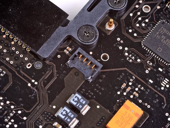
Use the flat end of a spudger to pry the hard drive cable connector up out of its socket on the logic board.
-
-
Deze stap is niet vertaald. Help het te vertalen
-
Remove the two short Phillips screws securing the small EMI shield to the logic board.
-
Remove the EMI shield from the logic board.
-
-
Deze stap is niet vertaald. Help het te vertalen
-
Use the flat end of a spudger to pry the trackpad cable connector up out of its socket on the logic board.
-
-
Deze stap is niet vertaald. Help het te vertalen
-
Use your fingernail to carefully flip up the keyboard ribbon cable retaining flap.
-
Use the tip of a spudger to pull the keyboard ribbon cable straight out of its socket.
-
-
Deze stap is niet vertaald. Help het te vertalen
-
Use the flat end of a spudger to pry the battery indicator cable connector up out of its socket on the logic board.
-
-
Deze stap is niet vertaald. Help het te vertalen
-
Grab the plastic pull tab secured to the display data cable lock and rotate it toward the DC-In side of the computer.
-
Pull the display data cable straight out of its socket.
-
-
Deze stap is niet vertaald. Help het te vertalen
-
Use the tip of a spudger or your fingernail to flip up the retaining flap on the keyboard backlight ribbon cable socket.
-
Pull the keyboard ribbon cable straight out of its socket.
-
-
Deze stap is niet vertaald. Help het te vertalen
-
Remove the following screws:
-
Seven 3.3 mm T6 Torx screws securing the logic board to the upper case.
-
Two 8 mm T6 Torx screws securing the DC-In board to the upper case.
-
-
Deze stap is niet vertaald. Help het te vertalen
-
Carefully lift the logic board assembly from the left side and work it out of the upper case, minding the port side that may get caught during removal.
-
-
Deze stap is niet vertaald. Help het te vertalen
-
Lift the logic board enough to gain clearance and use a spudger to pry the microphone up off the upper case.
-
-
Deze stap is niet vertaald. Help het te vertalen
-
Slide the logic board away from the port openings and lift the assembly out of the upper case.
-
-
Deze stap is niet vertaald. Help het te vertalen
-
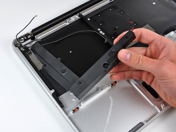
Remove the two Phillips screws securing the hard drive bracket to the upper case.
-
Remove the hard drive bracket from the upper case.
-
-
Deze stap is niet vertaald. Help het te vertalen
-
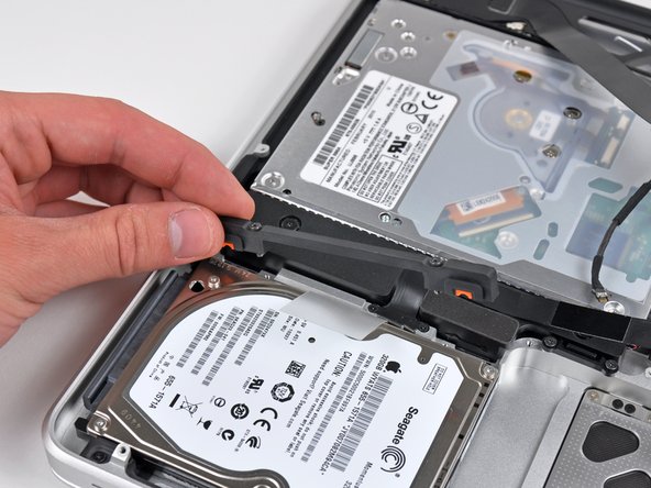
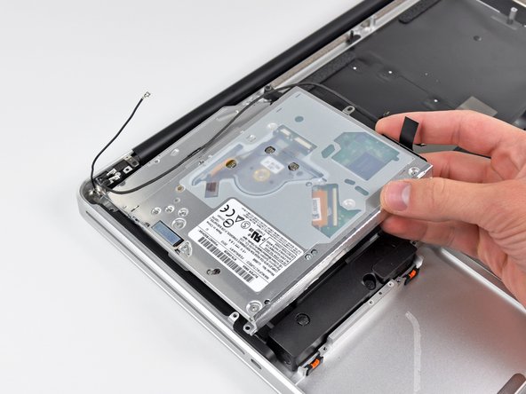
Using its attached pull tab, lift the hard drive out of the upper case.
-
-
Deze stap is niet vertaald. Help het te vertalen
-
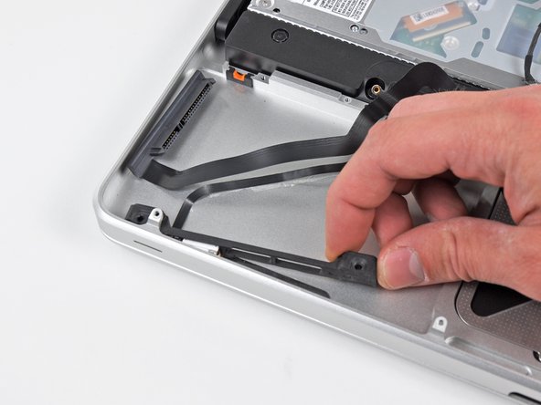
Pull the hard drive connector out of its socket on the hard drive.
-
Remove the hard drive and set it aside.
-
-
Deze stap is niet vertaald. Help het te vertalen
-
Remove the following four screws securing the hard drive/IR sensor cable to the upper case:
-
Two 2.5 mm Phillips screws.
-
Two 10 mm Phillips screws.
-
-
Deze stap is niet vertaald. Help het te vertalen
-
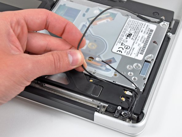
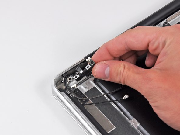
Carefully peel the IR sensor cable off the adhesive securing it to the upper case.
-
Pull the hard drive bracket/IR sensor housing away from the side of the upper case.
-
Remove the hard drive/IR sensor cable from the upper case.
-
-
Deze stap is niet vertaald. Help het te vertalen
-
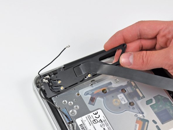
Use the tip of a spudger to pry all three AirPort/Bluetooth antenna connectors up off the AirPort/Bluetooth board.
-
-
Deze stap is niet vertaald. Help het te vertalen
-
De-route the three antenna cables from their channels in the AirPort/Bluetooth housing.
-
De-route the camera cable from its channel in the AirPort/Bluetooth housing.
-
-
Deze stap is niet vertaald. Help het te vertalen
-
Remove the following two screws securing the AirPort/Bluetooth housing to the upper case:
-
One 3.8 mm Phillips
-
One 8.6 mm Phillips
-
Remove the AirPort/Bluetooth assembly from the upper case, minding any cables that may get caught.
-
-
Deze stap is niet vertaald. Help het te vertalen
-
Remove the following three Phillips screws securing the optical drive to the upper case:
-
One 4.5 mm Phillips screw securing the optical drive bracket to the upper case near the fan.
-
Two 2.5 mm Phillips screws securing the optical drive to the upper case near the optical drive opening.
-
Remove the optical drive from the upper case.
-
-
Deze stap is niet vertaald. Help het te vertalen
-
Remove the following six screws securing the subwoofer and right speaker to the upper case:
-
Two 3.2 mm Phillips screws.
-
Two 12.3 mm Phillips screws.
-
One 2.5 mm Phillips screw.
-
One 8.3 mm Phillips screw.
-
Remove the subwoofer/right speaker from the upper case.
-
-
Deze stap is niet vertaald. Help het te vertalen
-
Remove the 8.6 mm Phillips screw securing the antenna/camera cable retainer to the upper case.
-
Remove the antenna/camera cable retainer from the upper case.
-
-
Deze stap is niet vertaald. Help het te vertalen
-
Remove the single 8.6 mm Phillips screw securing the display data cable retainer to the upper case.
-
Remove the display data cable retainer from the upper case.
-
-
Deze stap is niet vertaald. Help het te vertalen
-
Remove two of the three 6 mm T6 Torx screws securing the right side of the display to the upper case.
-
-
Deze stap is niet vertaald. Help het te vertalen
-
Remove two of the three 6 mm T6 Torx screws securing the left side of the display to the upper case.
-
-
Deze stap is niet vertaald. Help het te vertalen
-
Open your MacBook Pro so the display is perpendicular to the upper case.
-
Place your opened MacBook Pro on a table as pictured.
-
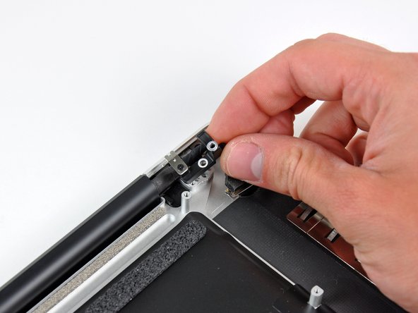
While holding the display and upper case together with your left hand, remove the remaining T6 Torx screw from the upper display bracket.
-
-
Deze stap is niet vertaald. Help het te vertalen
-
Remove the last remaining T6 Torx screw securing the display to the upper case.
-
-
Deze stap is niet vertaald. Help het te vertalen
-
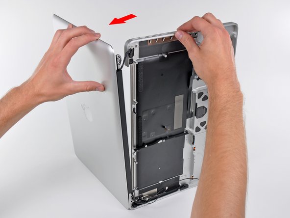
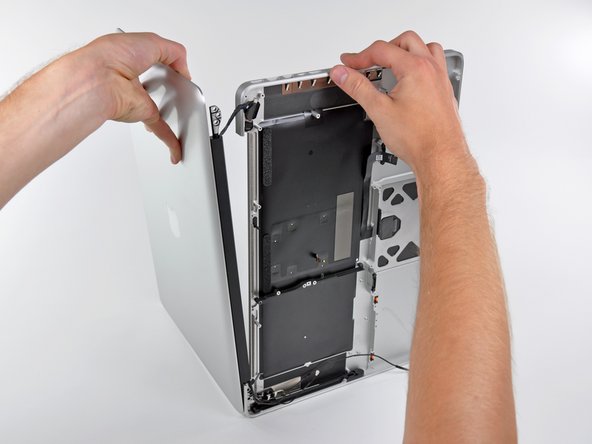
Grab the upper case with your right hand and rotate it slightly toward the top of the display so the upper display bracket clears the edge of the upper case.
-
Rotate the display slightly away from the upper case.
-
Lift the display up and away from the upper case, minding any brackets or cables that may get caught.
-


Annuleren: ik heb deze handleiding niet afgemaakt.
64 andere personen hebben deze handleiding voltooid.

8 opmerkingen
Great, easy repair (at least for me).
I only had problems with a 2.5 mm phillips screw, the one holding the right speaker assembly from the side. I needed to use a drill to drill it from the center away.
So 100% success, 1 screw less.
I am having a heck of a time reinserting this keyboard ribbon cable. The first time I powered up, only the left side of the keyboard worked. I tried reinserting, and all further attempts have resulted in no keyboard response at all. The ribbon is starting to "dogear" a tiny bit in the corners, so I am hesitant to try my current technique too many more times. I'd really like to do this correctly. Has anyone had luck slightly removing the logic board to aid in getting a better angle on inserting the cable? Any help would be appreciated!!!
A number of these steps are unnecessary to replace the upper case. For example, there is no reason why the hard drive needs to be removed. After getting to the steps where the upper display hinges are removed, I couldn't see any reason why the logic board needed removal. My advice would be to disconnect the battery. Then perform Step 21 (disconnecting the display cable). Then perform Step 32 (disconnect Airport/Bluetooth antenna cables). Then proceed to Step 37 and complete the guide from there. If you encounter any part that's in your way (perhaps the edge of the logic board might prevent the upper display case from being pulled away from the lower case), just go back through this guide and follow the directions to remove only that particular part. But just be aware that quite a few steps in this guide are not necessary, and it is certainly not true that "Replacing the upper case requires removal of nearly every component inside your MacBook Pro 15" Unibody Mid 2010."
The hard drive and logic board are installed in the upper case. How could you not remove them? You'd be rebuilding your computer with the new upper case, without a logic board or keyboard. You aren't confusing the upper case for the display, are you? This guide is about replacing the top case, which is the part where the keyboard is, not the display.
John M -