Inleiding
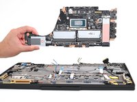
Follow this guide to replace the motherboard (aka system board) in your Lenovo ThinkPad T16 Gen 3 laptop.
This board contains the processor and the ports on the left side. If the ports on the right side of your T16 Gen 3 are malfunctioning, you may need to replace the I/O board.
Wat je nodig hebt
-
-
Completely shut down your laptop (don't just put it in sleep mode) and disconnect all cables.
-
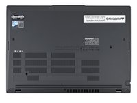
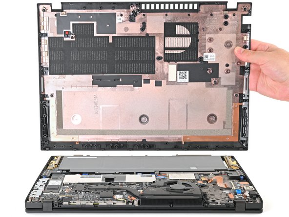
Flip the laptop upside-down, and rotate it so the screen hinge faces towards you.
-
-
-
Use a Phillips screwdriver to fully loosen the two captive screws securing the keyboard to the laptop.
-
-
-
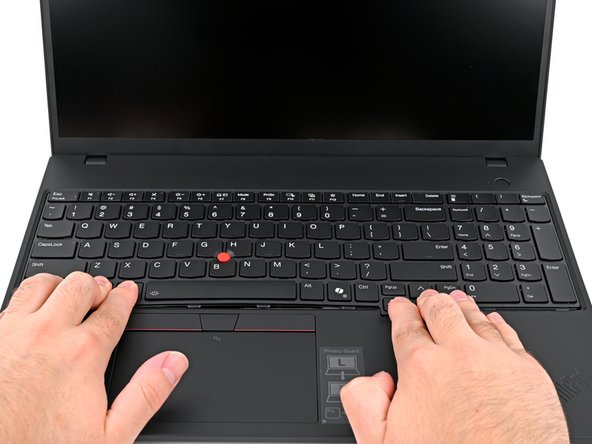
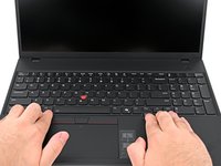
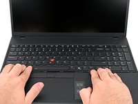
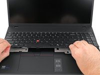
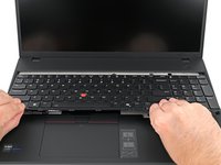
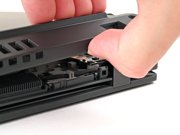
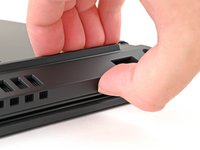
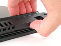
Place your fingers on the bottom edge of the keyboard.
-
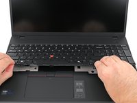
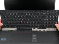
Push the keyboard towards the screen until you can lift the bottom edge.
-
Lift the bottom edge of the keyboard slightly off your laptop.
-
-
-
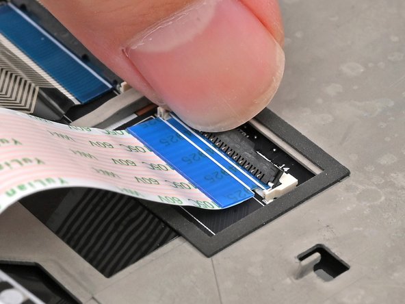
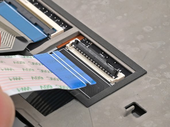
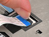
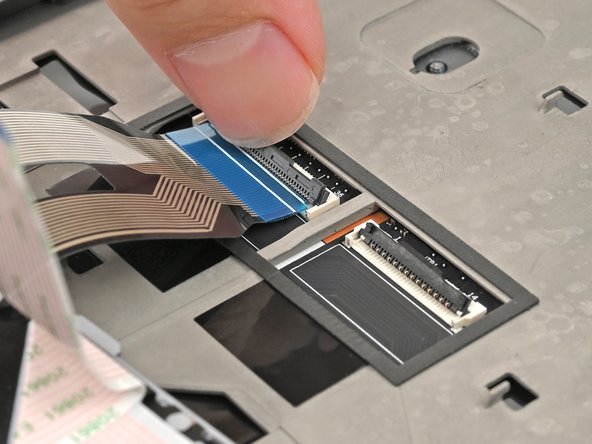
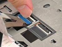
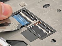
Use your fingernail or the flat end of a spudger to flip up the locking flap on the TrackPoint cable ZIF connector.
-
Use your fingers or tweezers to gently pull the cable out of its socket.
-
-
-
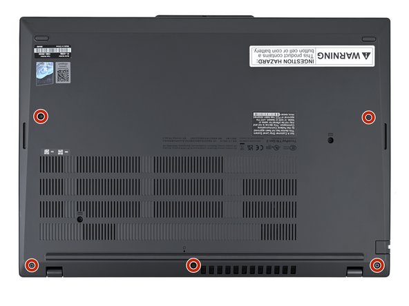
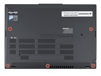
Use a Phillips screwdriver to fully loosen the five remaining captive screws securing the base cover.
-
-
-
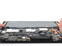
Insert your fingernail or an opening pick into the gap between the base cover and keyboard deck, next to one of the screen hinges.
-
Pry up the base cover until the clips unfasten.
-
-
-
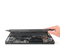
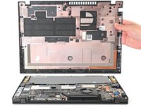
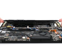
Grasp the base cover along the screen hinge edge and lift slowly to unfasten the remaining clips.
-
Lift and remove the base cover.
-
-
-
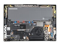
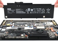
Use a Phillips screwdriver to fully loosen the two captive screws securing the battery connector.
-
-
-
Lift the edge of the battery with the connector to disconnect it.
-
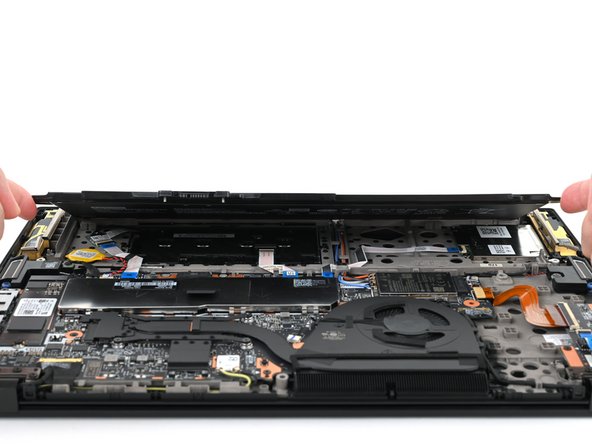
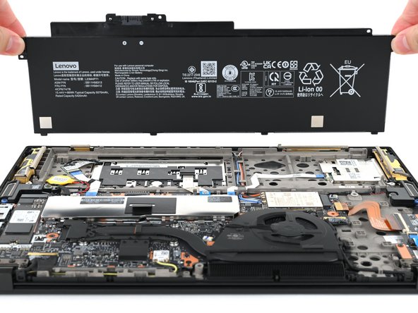
Remove the battery
-
Slide the plastic tabs on the long edge of the battery into their recesses in the frame.
-
Lower the battery into place so the connector goes over its socket.
-
-
-
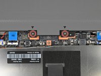
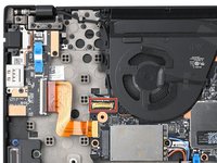
Use the flat end of a spudger or clean fingernail to gently push under the metal buckle of the camera cable connector to unclip it.
-
-
-
-
Hold the buckle and cable together and remove the cable from the clips holding it to the fan.
-
-
-
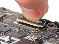
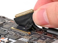
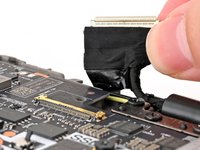
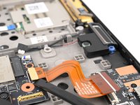
Use a clean fingernail or the flat end of a spudger to gently push under and lift the metal buckle of the display cable connector to unclip it.
-
-
-
Hold the buckle and cable together and pull up to separate the adhesive securing the cable to the motherboard.
-
-
-
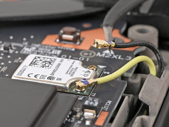
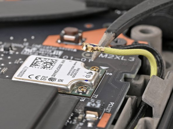
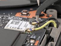
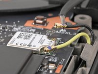
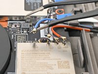
Insert an arm of your angled tweezers under the metal neck of one of the coaxial connectors on the Wi-Fi card and lift straight up to disconnect it.
-
Repeat for the other connector.
-
-
-
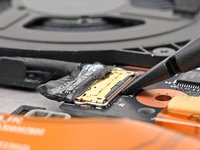
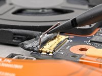
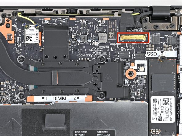
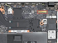
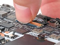
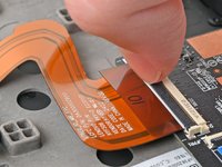
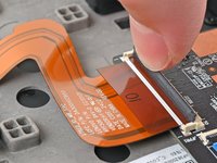
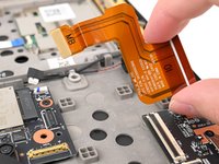
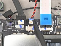
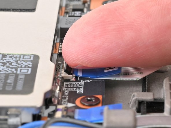
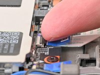
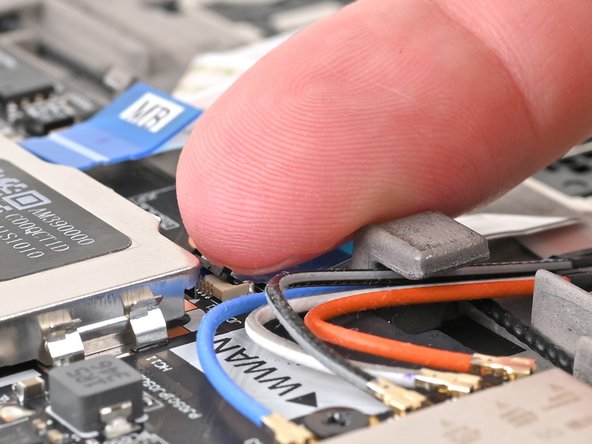
Use a clean fingernail or the flat end of a spudger to flip up the locking flap on the I/O board interconnect cable connector.
-
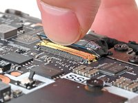
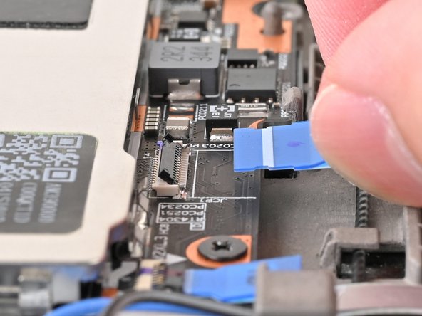
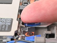
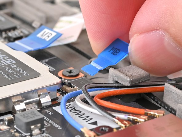
Use tweezers or your fingers to gently pull the cable by its pull tab out of its socket.
-
-
-
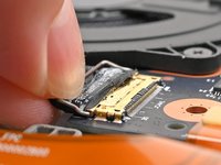
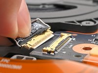
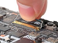
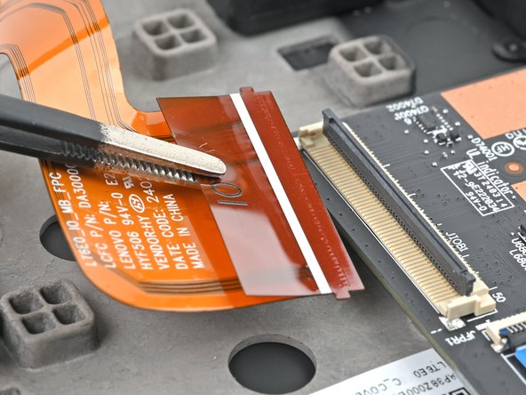
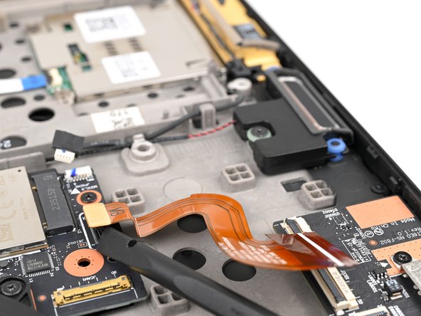
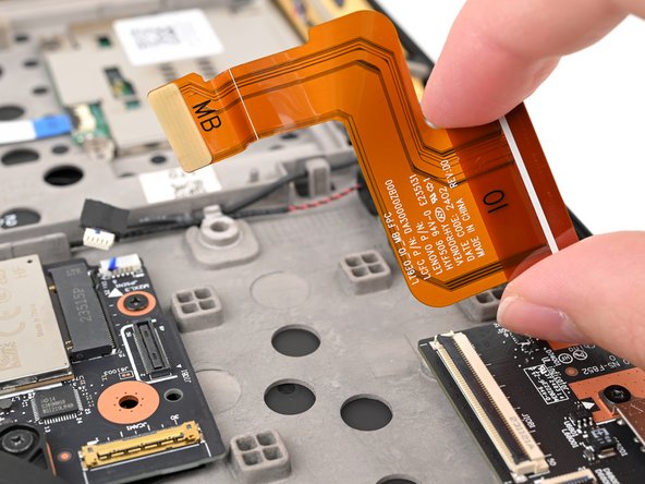
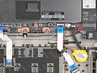
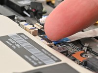
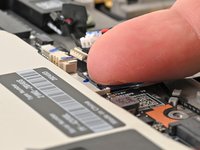
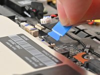
Insert the flat end of a spudger or a clean fingernail under a short edge of the interconnect cable press connector (located on the motherboard) and pry up to disconnect it.
-
Remove the interconnect ribbon cable from the laptop.
-
-
-
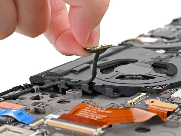
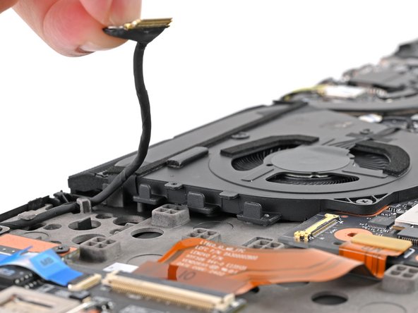
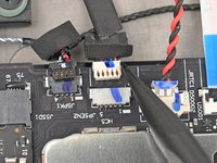
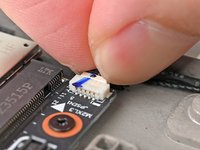
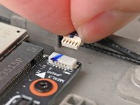
Use your fingernails to grip the right speaker connector by the lip near the back and gently pull the connector out of its socket (labeled"JSPK1").
-
Unplug the connector from the motherboard.
-
-
-
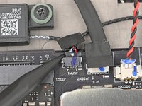
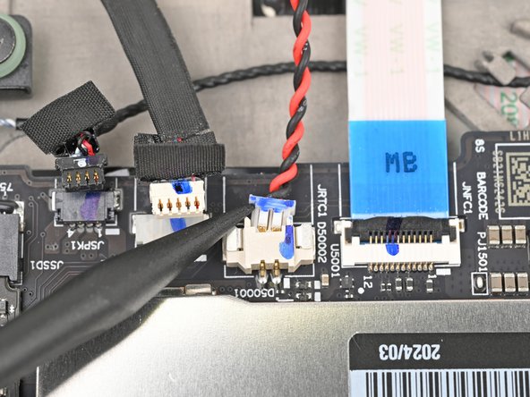
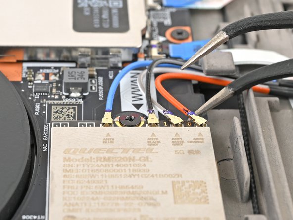
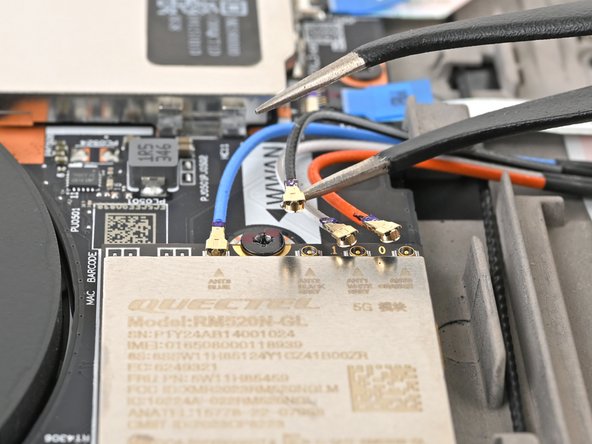
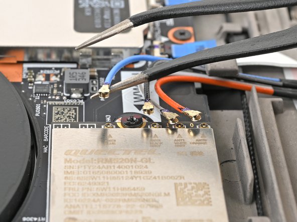
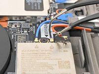
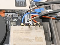
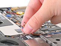
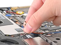
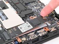
Insert one arm of your angled tweezers under the metal neck of one of the antenna coaxial connectors on the WWAN card and lift straight up to disconnect it.
-
-
-
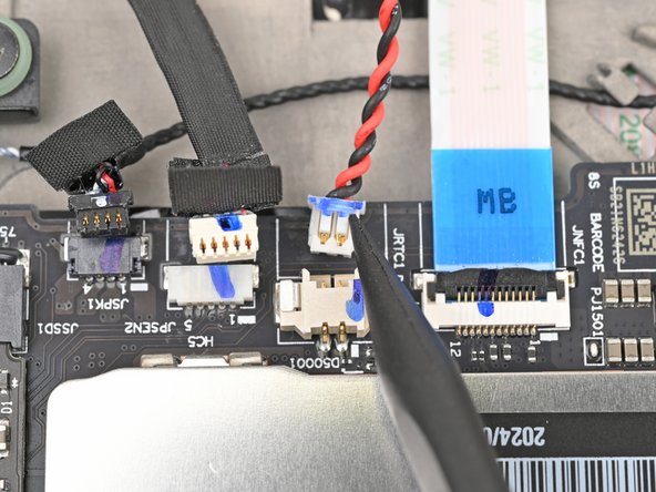
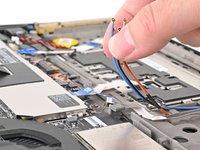
Hold all the antenna cables together and guide them out of their clip on the chassis.
-
-
-
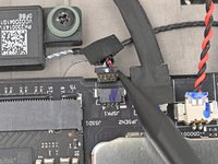
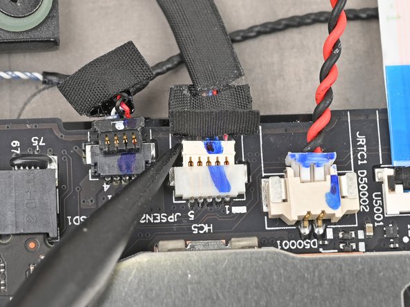
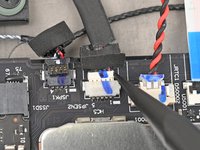
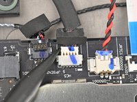
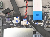
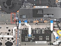
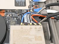
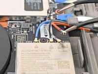
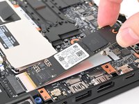
Use your fingernails to grab on the lip located at the back of the WWAN antenna connector labeled "JPSEN1."
-
Unplug the connector from the motherboard.
-
-
-
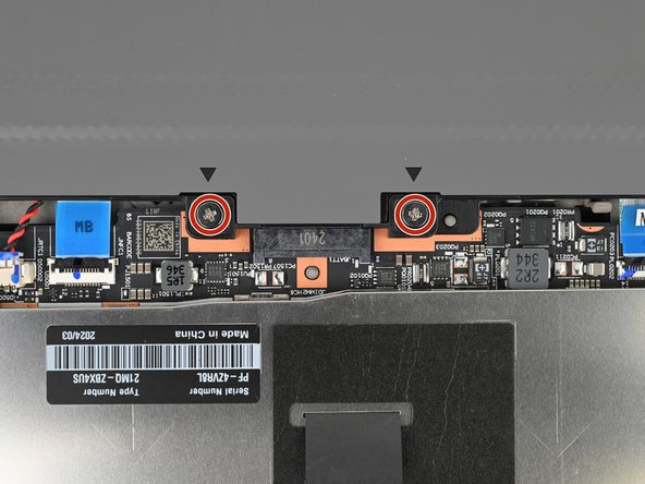
Use a Phillips screwdriver to remove the three 4 mm‑long screws securing the I/O bracket.
-
-
-
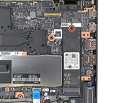
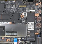
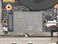
Use a Phillips screwdriver to remove the 4 mm‑long screw securing the SSD to the motherboard.
-
-
-
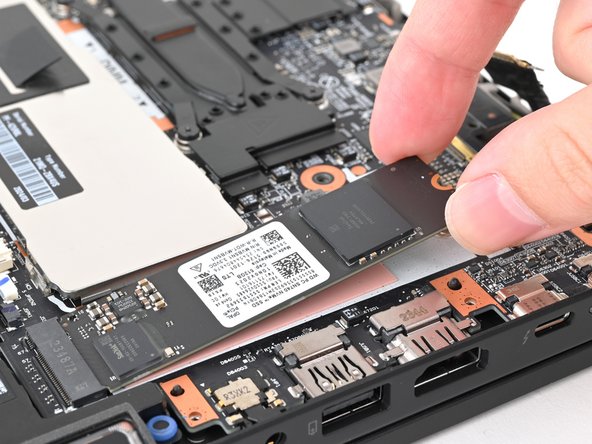
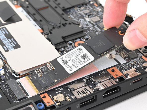
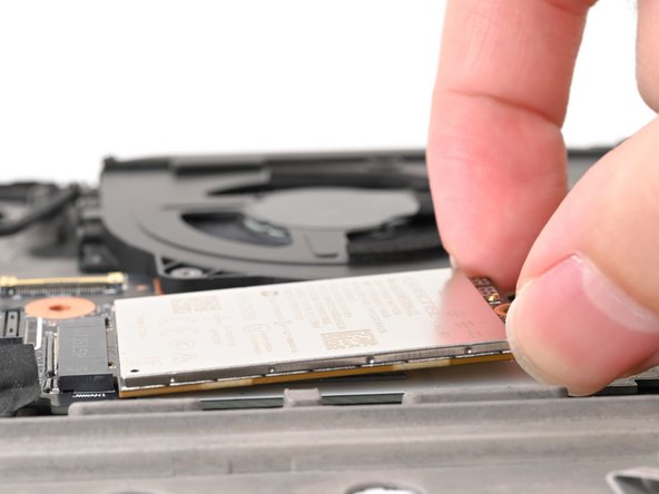
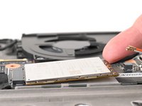
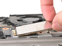
Use your fingernail or the flat end of a spudger to lift the edge of the SSD with a screw notch enough to grip it with your fingers.
-
Use your fingers to pull the SSD straight out of its socket and remove it.
-
-
-
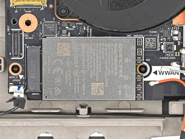
Use a Phillips screwdriver to remove the 4 mm‑long screw securing the WWAN card to the motherboard.
-
-
-
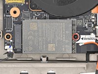
Use your fingernail to lift up the WWAN card enough to grasp it with your fingers.
-
Pull the WWAN card straight out of its socket and remove it from the laptop.
-
-
-
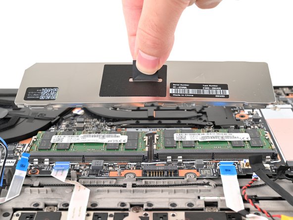
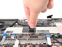
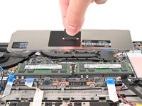
Grab the pull tab in the middle of the RAM shield and pull straight up to remove it from its clips.
-
-
-
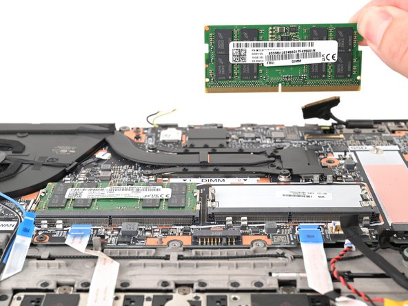
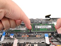
Use your fingers to simultaneously push the two metal tabs on the edges of the RAM module down and outwards to unlatch them—the RAM should pop up at a slight angle.
-
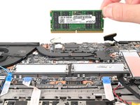
Remove the RAM stick.
-
Repeat the above process for the other stick of RAM.
-
-
-
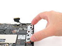
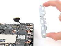
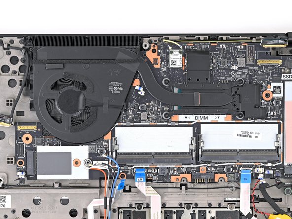
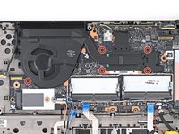
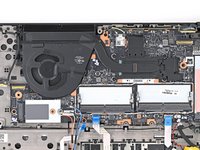
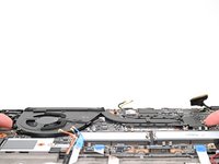
Use a Phillips screwdriver to fully loosen the five captive screws securing the fan and heatsink.
-
-
-
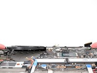
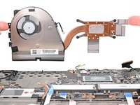
Grasp the fan and heatsink assembly by its edges and remove it from the laptop.
-
-
-
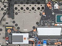
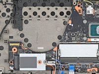
Use a Phillips screwdriver to remove the three 4 mm‑long screws securing the motherboard.
-
-
-
Use your finger to lift the motherboard by the edge closest to the fan.
-
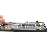
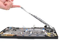
Raise the motherboard to a 45‑degree angle to free the ports from their cutouts.
-
Grip the edges of the motherboard and remove it.
-


Compare your new replacement part to the original part—you may need to transfer remaining components or remove adhesive and thermal backings from the new part before you install it.
To reassemble your device, follow these instructions in reverse order.
Take your e-waste to an R2 or e-Stewards certified recycler.
Repair didn’t go as planned? Try some basic troubleshooting, or ask our Answers community for help.

