
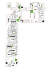
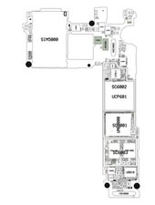
Bump on SHIELD CAN- PMIC on motherboard
One day without warning, my son's Samsung galaxy s7 phone would not turn on or show signs of charging. He took very good care of this phone and didn't put even a scratch on it or drop it. We replaced both the battery and display. Before gluing the phone back together we tested it, and it still shows no sign of life. We bought the phone new on eBay, but when we opened it two years later when it stopped working, it was obvious we had been scammed. There was a big F written with sharpie pen where the serial number should have been on the sticker, and other stickers, stamps, and internal scratches of previous repair. Besides this, there is a big bump on the PMIC shield on the motherboard. Does anyone know what this indicates, and if it is repairable? We really want to recover the data from this motherboard. But the area that appears damaged is either where the storage is located or close to it (from what I gather from research). Are there any good tutorials on using a multimeter to test the different parts of the motherboard? I don't know where to place the points of the multimeter to test the voltage of the power button, and if the battery needs to be inserted into the phone to be able to test the voltage of that part. Specifically, it is part R7027 that the voltage level needs to be tested at. I just don't know how to do this. It is hidden by that same shield with the bump on it. Can the power key FPCB be replaced easily? Images of the motherboard are posted below. The bump stands out pretty well.
(I used the schematic for S7 SM G930F at simplecodehub.com posted by blue-thunder to reference the parts list, location, and flow of repair)
1) What does the bump on the PMIC shield indicate?
2) tutorials on testing different parts of the motherboard?
3) Where to place the points of the multimeter to test the voltage of the power button at R7027.
4) Does the battery need to be in the phone to test voltage of parts on the motherboard?
5) Can the power key FPCB be replaced?
6) Can the PMIC be fixed without losing the phone data?
7) What would have caused these issues? Something by the user, manufacturer, or refurbishment?
This may not be worth it to repair financially, and I am okay with that. I am in it for the learning experience, and the slight chance at saving my son's minecraft worlds and pictures that are on this phone. Thank you for your time. I am a complete novice, so I appreciate any help and respectful guidance.


Is dit een goede vraag?


2 opmerkingen
Is the charging port ok? All pins inside ok and solder joints solid? Don't suppose you have access to a power meter to see if the board is pulling any power from the charger.
door [deleted]
Thank you for your reply! There are no visible signs of damage to the port or looseness. This phone has wireless charging capabilities, so we had tried charging it wirelessly before taking it apart. The charger lights up when it starts charging a phone. We tested our other wireless charging phones on the same charger. When we put the dead phone on the wireless charger, the charger DID recognize it and acted the same as while charging our other phones. The phone itself did not respond in any way. Not even the blinking LEDs work. No dead battery screen, flash or vibration. Inside the phone, we don't see any damaged pins or cables internally. I haven't taken the shield off yet because I have never soldered before and wondered if there was a way to test it without taking it off. I have a Fluke electronics multimeter combo kit 179/EDA2 Kit. I am not sure if it has functionality to read if it is pulling power from the charger. Would the battery need to be connected in the phone to test this?
door Erin