Ga door naar hoofdinhoud

Repair information and guides for corded and cordless power drills.

111 Vragen Bekijk alle

Why doesn't my charger work?

  • The charger for my Ryobi One plus BCL14181H doesn't work. I took to pieces it and saw that one of resistance and transistor were burned. I replaced the resistance, but i can't see the number of transistor. It would be good if someone makes photos of sceme and of transistor and writes the number of this transistor.

*

Block Image

*

Block Image

*

Block Image

*

Block Image

*

Block Image

Thanks for all who will aid with this problem.

Beantwoord! Bekijk het antwoord Dit probleem heb ik ook

Is dit een goede vraag?

Score 2
12 opmerkingen

Attempting to fix this type of equipment is dangerous, and even deadly. A typical power supply contains capacitors large enough to deliver a significant electrical shock. Any mistakes in resoldering this could result in bad things. You can find out about why here: Device Safety.

door

Thank you for comment. I know safety rules. I think i waited enough time to discharge capacitors.

door

mosfet 9565bgh.

door

I have the same problem, I have 4 chargers with the same part as yours burned, was your repair successful

door

put a small alli heatsink on it witha bit of silicon when this mosfet goes short it also shorts one of the avalanch diodes two there side by side it can also blow the driver for the switchmode power transformer and also the load resistor along side it . The parts are available on the net

door

7 commentaren meer tonen

Voeg een opmerking toe

15 Antwoorden

Gekozen oplossing

It's mosfet 9565bgh.

Was dit antwoord nuttig?

Score 3

3 opmerkingen:

Thank you! I'll try this transistor.

door

I had the same problem but it's much bigger the PCB is fried and don't know we're the connections goes

door

It's working!!!

Model: BLC14181H

Replaced:

-9565BGH Mosfet

-MBR5200 Diode (200v 5A)

-N Channel Mosfet NDF04N60ZH (600v 2A)

*heatsink on the 9565BGH

Thank you so much to all the people in the comments :)

door

Voeg een opmerking toe

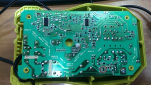
Seems to be a thing with these chargers. This is what I have failed on this one:

R2 (470 ohm), R3 (220 ohm), R4 (150 ohm), RS1 (0.43 ohm) - all open circuit

Q1 (NDF04N60ZG) - shorted

IC3 (SG6848) - probably blown

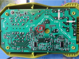
The above components are PWM control and the main chopper transistor on the primary side. Normally a blown chopper will take out the main fuse, but there isn’t even one in this design. Instead they rely on RS1 (fusible resistor I’m assuming) to go open when the chopper shorts. This is a really crappy design, since the main filter caps would be a at 400V DC in the fault condition. There’s no bleeder resistor incorporated either, so if you go working on this, make sure you discharge the cap.

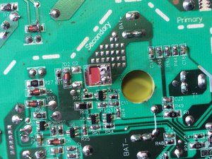
D3/D9 (SB5200) - one shorted, other ok. These are the main rectifiers on the secondary side. I’ve seen this go short in other supplies, but good designed ones will shut down the PWM to prevent damage. Not this one it seems.

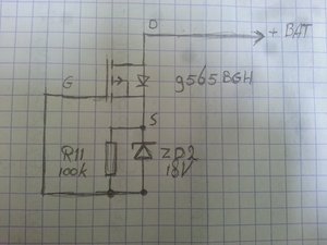
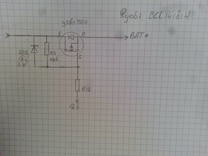
Q2 (9565BGH) - Shorted (in fact had a hole in it).

Q4 only reads 0.6V on two pins, but I suspect this is actually a zener diode in a SOT346 package. Only see 202 or 702 on the package. Be nice if I had a schematic.

Just an awful design as far as switch modes go. Haven’t seen this much destruction since the old days of self oscillating supplies. Anything with a PWM IC usually has over current/voltage protection to shut everything down. Just a poorly designed and CHEAP supply. I was half through repairing it and I’ve now decided to bin it. It’ll only blow up again.

Was dit antwoord nuttig?

Score 3

1 Opmerking:

I have just received one with the same problem.

door

Voeg een opmerking toe

I have the same problem just different part.

Can someone tell me markings of this chip (IC1)?

Block Image

Thank you!

Was dit antwoord nuttig?

Score 2

1 Opmerking:

ic1 = sg6853 (sg6848)

door

Voeg een opmerking toe

Hello

This 2x3 pins IC is : 6853H37

Hope this will help

Was dit antwoord nuttig?

Score 0
Voeg een opmerking toe

same problem after you fit the new one glue a small piece of alli or something like that as a heatsink.

Was dit antwoord nuttig?

Score 0
Voeg een opmerking toe

Where can you buy this part 6853H37 . I have the same problem with my charger but I can't found this part or a datasheet is also nice .

Thanks for help .

Was dit antwoord nuttig?

Score 0
Voeg een opmerking toe

Mosfet 9565BGH = Mosfet FDD4685

Was dit antwoord nuttig?

Score 0

1 Opmerking:

IRFR5305 should also be suitable for replacement.

door

Voeg een opmerking toe

Hello,

My Ryobi Charger Board has problem as below:

- The Diode MBR5200 was short circuit

- The Mosfet Mosfet 9565bgh was burned

- The Zener Diode ZD2 which is closed the Mosfet 9565bgh was burned.

I have replaced the Diode MBR5200 and the Mosfet 9565bgh, but I did not know what is the Zener Diode ZD2 (Regulated Voltage = ?)

Please advise with thanks,

Anh Le

Was dit antwoord nuttig?

Score 0

4 opmerkingen:

The zener diode voltage should be less than the Drain-Source Breakdown Voltage.

door

iZD2 = 18volts. I also have a charger that broke due to 9565bgh failure. This really needs a heat sink. Bad design.

door

16volts Zener diode

door

Bonsoir à tous. Voilà le lien où trouver le schéma (Il suffit de taper la référence presque de n'importe lequel appareil électronique: https://elektrotanya.com/list_wanted Moi j'ai le schéma envoyez moi vos E-mail je vais vous le transférer pour tous afin d'aider autrui. Moi j'ai eu le même problème j'ai changé le mosfet par un IRF 9540N il met trop de temps pour charger. 6 mois après les diodes de redressement sont encore cramé j'ai changé etc hélas il ne charge pas (le témoin rouge clignote comme quoi il charge hélas rien. J'arrive pas à le réparer car j'arrive pas à trouver les données de la puce ADS2110 sur Datasheet ni sur Google. Conclusion je ne connais pas son fonctionnement. Cordialement

door

Voeg een opmerking toe

Can someone tell me markings of the IC3?

Was dit antwoord nuttig?

Score 0

1 Opmerking:

Ic3 is adc2011

door

Voeg een opmerking toe

Where does the 9565BGH get it’s gate from? My continuity check reveals to be connected to only ZD2 and R11.

Block Image

  • EDIT ***

After some more exploring I have found out that the gate is driven by R12 and Q4. When the 9565BGH blew it must have damaged the copper trace between the gate, ZD2 and R11. To make it work again I had to replace the mosfet, ZD2 and the two MBR5200 schottky diodes ( one was short ciruited and I did not want to take any chance with not replacing the second one) and re-trace from R11 to the gate of the mosfet. I have added the circuit from a small part of the reverse enginered circuitboard. Hope this helps someone.

Block Image

Was dit antwoord nuttig?

Score 0

1 Opmerking:

For R11 does it matter the wattage, I can probably source a 9565BGH and diodes but not sure how to find correct resistor R11. On my circuit board it isn't labelled at all not 100k or 104, just blank. Also my multi meter won't read it not sure if it blown or just too small of a reading for multimeter to pickup.

I found a few random circuit boards at home with Zenier diodes with blue marks but afraid to try as have no idea of their voltage.

Thanks

door

Voeg een opmerking toe

Hello,

Can someone tell me the voltage of ZD1 please?

Thank you in advance

Was dit antwoord nuttig?

Score 0

2 opmerkingen:

Please help me I get 15 v dc in ryobi charger

door

hello,

Does anyone know the value of Q4?

Thanks

door

Voeg een opmerking toe

Hey,

I think I have a similar problem, mine seems to have burnt out and potentially some of the parts around it. I've attached a photo, could I please ask your help to identify the parts.

The main part I need is AP9565BGH I believe

Thank you!

Block Image

Was dit antwoord nuttig?

Score 0
Voeg een opmerking toe

I replaced many parts described by posters here. Worked for a couple goes. Today all seemed normal with flashing green light but doesn't progress with charge. Hmmm. Battery tech sux.

Was dit antwoord nuttig?

Score 0

2 opmerkingen:

Did you get any further with this?

door

Bonsoir ! J'ai un problème similaire au votre. Dans mon cas c'est la LED rouge qui clignote pas la verte mais aucune progression. J'ai installé une autre batterie fonctionnelle avec la perceuse c'est pareil. Donc le problème réside dans le chargeur non dans la batterie. Cordialement

door

Voeg een opmerking toe

Hi guys, can I put any MOS FET

Was dit antwoord nuttig?

Score 0
Voeg een opmerking toe

It depends on the output power if positive p channel if negative n channel and also depends on the voltage and current of the circuit board.

Hope this help.

Was dit antwoord nuttig?

Score 0
Voeg een opmerking toe

Voeg je antwoord toe

Nikita zal eeuwig dankbaar zijn.
Weergavestatistieken:

Afgelopen 24 uren: 0

Afgelopen 7 dagen: 14

Afgelopen 30 dagen: 82

Altijd: 39,734