Wat je nodig hebt
-
-
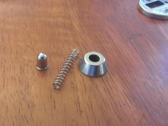
Hier zien we het apparaat. Het is overwegend goedkoop plastic en dun gestanst metaal.
-
Het ziet en voelt er erg licht en goedkoop uit, geen goed teken. Maar zoals ze zeggen, beoordeel een boek niet op de omslag.
-
-
-
-
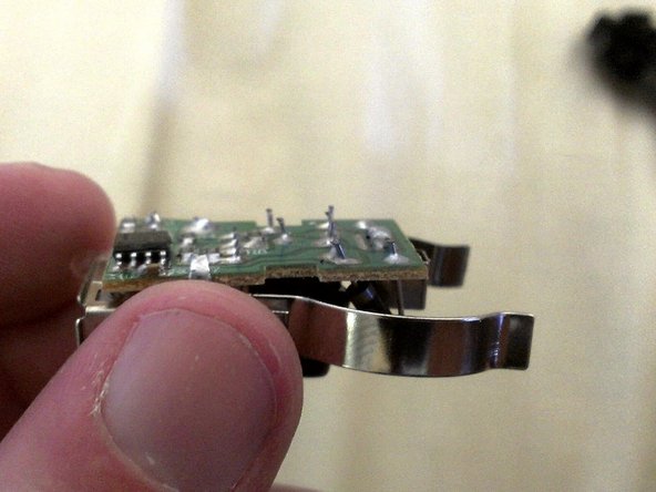
Laten we naar de andere kant kijken. De draden (in het rode vakje) zijn VEEL te lang. Vergelijk hun lengte met die op de USB-connector (in blauw). Hoewel het solderen er goed uitziet, tonen de lange draden een algemeen gebrek aan aandacht voor detail en kostenbesparingen.
-
Nu kunnen we de printplaat in het algemeen goed bekijken. Des te meer tekenen van kostenbesparingen. Het soldeermasker (het spul dat de print groen maakt) heeft enorme lege ruimtes rond de soldeerpads. Je kunt daar duidelijk de bruine print zien. Dit verhoogt de risico's op kortsluiting etc. Opnieuw goedkoop ontwerp.
-
Het hoofd-IC lijkt een MC34063 regelaar te zijn. Een echt werkpaard op het gebied van USB-laders. Hoewel dit IC tot 1,5 A kan aansturen, wordt het slechts als goed beschouwd voor maximaal 700 mA continu voordat warmte een probleem wordt. Oh Oh.
-
-
-
Hier zien we het schema uit de database.
-
In de volgende afbeelding zien we het schema dat in het apparaat wordt gebruikt. We zien dat veel waarden zijn veranderd.
-
De grootste verandering is dat Rsc 0,22 ohm is. Dit geeft een Ipk van 1,36A, wat een Iout Max van 0,68A oplevert. Dit is VER verwijderd van de geciteerde 1A.
-
Ook zijn de ingangs- en uitgangscondensatoren verkleind tot respectievelijk 10uF en 100uF. Dit betekent dat we een VEEL grotere rimpel op de uitvoer zullen zien. Mogelijk valt het buiten de USB-specificatie en brengt het aangesloten apparaat gevaar.
-
Heel eenvoudig: het apparaat is op zijn best een omgedoopte 500mA of 750mA USB-oplader. Het is NIET geschikt voor 1A, ondanks wat de sticker op de behuizing zegt.
-


Met dank aan deze vertalers:
100%

Toon Konings helpt ons de wereld te herstellen! Wil je bijdragen?
Begin met vertalen ›

11 opmerkingen
I tore down the same device with much the same comments - http://mm0hai.net/blog/2012/08/01/Messag...
Could you do a tear down of the more advanced usb car chargers, it would be interesting on how these are made and work
The right conclusion of R(3.6K) it has to be connected to the right conclusion of L (220uH).
I have already ordered a charger from the best seller of Amazon
Looking at the pic in step 6, it would appear the two data pins are shorted together, tied to +5V via a 75k-ohm resistor, and tied to ground via a 45k-ohm resistor. The resultant voltage divider should hold the two data pins at about +2V. As the data pins have 0V between them, any remotely modern cell phone will recognize this as a charger. An Apple device would recognize this as a 500ma charger, and most recent Android devices mimic Apple's scheme for identifying chargers.
The de-rated capacitors were likely deemed sufficient to regulate the ripple at 500ma. Such cost-cutting (and exaggerated specs) is par for the course with products manufactured and designed in China. My experience is that these things reliably (but slowly) charge my iPhone, and I can get them at the Dollar Tree.
It's been my experience these things work reliably with my Apple devices,
Just did some load testing with one of these, probably good for 500mA. At .55A over time the voltage will still drop out. I've seen chargers that use the MC34063 put out an amp easy. This one could if they did a good job with it, but they cheaped out. It's pretty much garbage for most applications.
Edit: Just took it apart, it this one is designed with another chip, The AD84064. Looks like a it's probably a cheaper alternative, and a worse performer.
The schematic doesn't show the LED. I would like to know if it can be removed without affecting the operation. I don't need it, don't want it, and it just consumes power.
I think it is driven off of the 12V line with a resistor. You should be just fine to remove it.
PedroDaGr8 I am building a cigarette lighter device with some proprietary functionality. I would love to get your input on this project. please reach out to me at txwinder@gmail.com