Inleiding
Is your iMac dead to the world? A fried power supply could be the problem.
Wat je nodig hebt
-
-
Orient the iMac face-side down on a table with the bottom edge facing yourself.
-
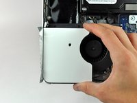
Remove the two Phillips screws securing the access door to the bottom grille of your iMac.
-
-
-
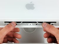
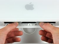
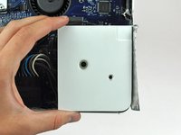
Remove the three T8 Torx screws securing the front bezel to the rear case along the lower edge of the iMac.
-
-
-
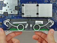
While holding the RAM arms in with your thumbs, lift the lower edge of the front bezel enough to clear the rear case.
-
-
Gereedschap gebruikt in deze stap:Plastic Cards$2.99
-
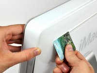
Insert a plastic card up into the corner of the air vent slot near the top of the rear case.
-
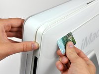
Push the card toward the top of the iMac to release the front bezel latch.
-
Pull the front bezel away from the rear case.
-
Repeat this process for the other side of the front bezel.
-
If the bezel refuses to release, try pressing the lower edge back onto the rear case and repeat this opening process.
If your computer has ever been worked on by an authorized Mac repair shop, this step may not be needed. I was able to skip this step after lifting the lower edge of the front bezel. Front bezel lifted off easily.
-
-
-
Lay your iMac stand-side down on a table.
-
Lift the front bezel from its lower edge and rotate it away from the rest of your iMac, minding the RAM arms that may get caught.
-
Lay the front bezel above the rest of the iMac.
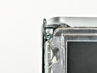
My A1145 seems to be attached, somehow, on the top via some silver looking strips. It does not seems to want to come off. Is that the wireless?
NO they are clamps on each of the top inside corners of the outside bezel (frame ) if you use a Heavy Spudger Tool & pry not too hard just slightly between the bezel (side) and the display (side) this should pop each off usually by just popping one or the other sides the second will automatically pop as well.
-
-
-
Peel the lower EMI shield off the lower edge of the iMac and off the two vertical 4" sections on either side of the iMac.
-
-
-
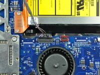
Remove the two T6 Torx screws securing the display data cable connector to the logic board.
-
-
-
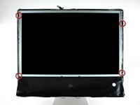
Remove the four recessed T10 Torx screws securing the display to the rear case.
The 64 Bit Driver kit does not include a thin-enough, thin-shafted T10 Torx screwdriver. Where to get one of these?
-
-
-
Lift the display until it is nearly perpendicular to the rear case.
-
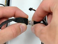
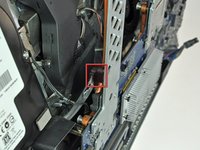
Disconnect the remaining two inverter cables (shown in red) by pulling their connectors toward the top edge of your iMac.
Steps 17 and 18 are not strictly necessary if one simply props up the LCD display into a vertical position while the hard drive is removed and replaced. It worked for me anyway!
I would like to send out a big thank you to Andrew Bookholt for submitting this extremely helpful guide!
Mark Orwoll
-
-
-
-
While holding the display perpendicular to the rear case, pull it upward to peel off the EMI shield stuck to its upper edge.
If you are changing the power supply - this is a good point to remove the screws to the old power supply to see if the connectors (both of them) are accessible. If you can gently (but firmly) pull the power connector out from under the chassis, you can install the new unit at this step - saving hours of work.
-
-
-
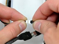
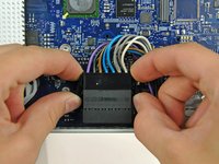
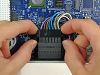
Disconnect the IR board cable by pulling its connector away from the socket on the IR board.
-
-
-
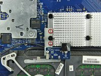
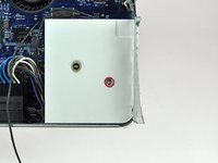
Remove the following seven screws securing the logic board to the rear case:
-
Three coarse-thread T10 Torx.
-
Three fine-thread T10 Torx.
-
One long coarse-thread T10 Torx.
Confirmed - is the same in my computer.
-
-
-
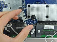
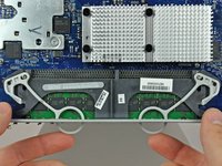
Rotate the top of the logic board toward yourself slightly.
-
Pull the right edge of the logic board toward yourself slightly to free the I/O ports from the rear case, being careful not to bend the board.
-
Continue rotating the board toward yourself until you have enough room to reach the SATA connector, shown in the next step.
-
-
-
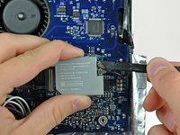
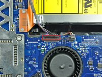
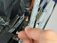
Continue rotating the board toward yourself until you have enough room to reach the SATA connector (shown in red).
-
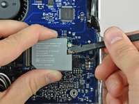
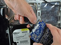
Insert the blunt end of a metal spudger between the SATA connector and its socket. Twist the shaft of the metal spudger to separate the connector from its socket.
-
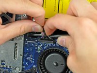
Disconnect the SATA cable from the logic board.
-
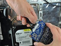
Lift the logic board out of the rear case by its edges, minding any cables that may get caught.
-
-
-
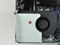
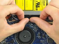
If necessary, remove the yellow kapton tape covering the AC-in cable.
These pictures show the view with the large central heatsink removed. You don't actually have to remove this, but you will then have to remove the AC-in cable from the left of the chassis member, rather than from the right (as shown). You can do this by unscrewing the power supply board first (4 screws) and then moving it slightly to the left so that you can access the AC-in cable.
-


To reassemble your device, follow these instructions in reverse order.
To reassemble your device, follow these instructions in reverse order.
Annuleren: ik heb deze handleiding niet afgemaakt.
40 andere personen hebben deze handleiding voltooid.

5Gids Commentaar
The images on this stage show the heat shield, cpu and associated pipework as removed but these steps are not included in the inbstructions
Sorry about that, the guide should be fixed now.
Step 40 Sorry, I didn't notice that someone had already commented. The fine threaded (orange) and course threaded (red) screws at the bottom of the machine are reversed. Just need to switch the circles on these two. Anybody know how to work with the images for the manual?
As you remove the screws during these steps, place them on a towel or a piece of cardboard. With a Sharpie label a piece of masking tape with the step number from which they were taken from. Then place the removed screws under the tape.
This ongoing step will aid in you having control on your reassembly without searching for and identifying the size and length all the screws that you are about to remove.
R51801 - Antwoord