Deze versie kan foutieve bewerkingen bevatten. Schakel over naar de recentste gecontroleerde momentopname.
Wat je nodig hebt
-
-
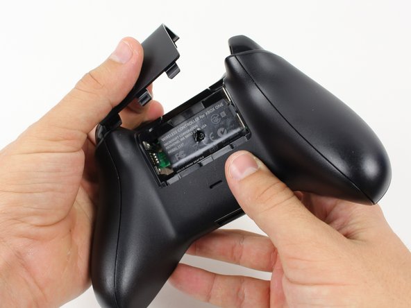
Pak de controller stevig vast om de zijhandgrepen te verwijderen en klem een spudger in de naad tussen de voorkant en de handgreepplaten.
-
Wrik de zijplaat los van de voorplaat door de spudger heen en weer te bewegen. Je moet dit helemaal rond de naad van de zijplaat doen.
-
-
-
Gebruik een schroevendraaier en maak een gaatje direct in het midden van het label.
-
Verwijder de vijf 10 mm-schroeven aan de achterkant van de controller met behulp van de T8 Security Torx-schroevendraaier.
-
-
Deze stap is niet vertaald. Help het te vertalen
-
De-solder the soldered joints while holding the red and black wires down on the top motherboard.
-
De-solder the black and gray wires that are attached to the top motherboard.
-
Remove the rumble motors and set them aside.
-
-
-
Deze stap is niet vertaald. Help het te vertalen
-
Unscrew the two 7mm T6 screws located near the rumble motor sockets.
-
-
Deze stap is niet vertaald. Help het te vertalen
-
Firmly grip sides of motherboard near the middle.
-
Lift upwards while slightly wiggling the motherboard forward and backward.
-
-
Deze stap is niet vertaald. Help het te vertalen
-
Remove the yellow tape holding the wires in place on the front of the controller.
-
-
Deze stap is niet vertaald. Help het te vertalen
-
Unscrew the two 7mm T6 Hex screws located on underside the triggers.
-
-
Deze stap is niet vertaald. Help het te vertalen
-
Remove the rumble motors from its socket and pull the wire with it.
-
-
Deze stap is niet vertaald. Help het te vertalen
-
Remove the six T6 Torx screws located on the bottom motherboard.
-
-
Deze stap is niet vertaald. Help het te vertalen
-
Remove the bumpers by prying them off of the pegs that secure them, using a spudger. They are located on the front and back of the controller.
-
-
Deze stap is niet vertaald. Help het te vertalen
-
Lift the piece surrounding the Home button off of its pegs.
-
Pry it off of the other side, using a spudger on the pins.
-


Annuleren: ik heb deze handleiding niet afgemaakt.
28 andere personen hebben deze handleiding voltooid.
Team

Cal Poly, Team 20-15, Maness Winter 2015 Lid van Cal Poly, Team 20-15, Maness Winter 2015
CPSU-MANESS-W15S20G15
5 Leden
50 handleidingen geschreven
11 opmerkingen
Is de-soldering optional?
Considering the placement of wires attached by solder on both sides of the top board, it would be quite difficult to reach anything beneath it otherwise. I suppose it depends on what you're trying to achieve.
In any case, you might as well try to move it without desoldering if desoldering is going to be an issue. Make sure not to pull hard, though.
Liam Gow -
I have a question... Will the motherboard you can get at the store here work it the newer controllers with built in headphone jack?
I would expect not, I'm afraid. The motherboards will probably have different circuitry, even if the shapes are the same, which they may not be.
Liam Gow -
The position/mounting of the LB and RB buttons on the motherboard piece between the day-one/sans-jack and the newer 3.5mm jack (non-Slim) boards are completely different.
The older revision motherboard has the mountings inverted (pointing downwards to the south end-headset attachment port- of the controller) compared to the newer ones.
The newer ones have the circuit with the bumper buttons mounted pointing to the north end toward the bumpers on the top of the controller.