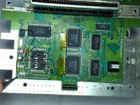
Ga door naar hoofdinhoud
Word lid van de reparatiegemeenschap - Account aanmaken

SNES 2CHIP 50/60 Hz Switchless Mod + LED Mod

Wat je nodig hebt

  1. SNES 2CHIP 50/60 Hz Switchless Mod + LED Mod, Motherboard: stap 1, afbeelding 1 van 1
    • Remove the two Phillips two 11.6mm screws that connect the front shield to the motherboard.

    Vraag FixBot

    Voeg opmerking toe

  2. SNES 2CHIP 50/60 Hz Switchless Mod + LED Mod: stap 2, afbeelding 1 van 1
    • Lift the front shield straight up to remove it from the motherboard.

    Vraag FixBot

    Voeg opmerking toe

  3. SNES 2CHIP 50/60 Hz Switchless Mod + LED Mod: stap 3, afbeelding 1 van 1
    • Remove the two silver 15.6 mm Phillips #2 screws on either side of the 62 pin connector.

    Vraag FixBot

    Voeg opmerking toe

  4. SNES 2CHIP 50/60 Hz Switchless Mod + LED Mod: stap 4, afbeelding 1 van 1
    • Remove the 11.8 mm Phillips #2 screw near the rear of the SNES.

    Vraag FixBot

    Voeg opmerking toe

  5. SNES 2CHIP 50/60 Hz Switchless Mod + LED Mod: stap 5, afbeelding 1 van 1
    • Lift the motherboard straight up to remove it.

    Vraag FixBot

    Voeg opmerking toe

  6. SNES 2CHIP 50/60 Hz Switchless Mod + LED Mod, The Two Chips: stap 6, afbeelding 1 van 1
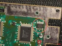
    • The Two Chips that you need on your Super Nintendo

    • This mod only works on original Super Nintendo with 2 Chips, this mod doesn't work on the 1 Chip Snes.

    Vraag FixBot

    Voeg opmerking toe

  7. SNES 2CHIP 50/60 Hz Switchless Mod + LED Mod, The Lockout Chip: stap 7, afbeelding 1 van 2 SNES 2CHIP 50/60 Hz Switchless Mod + LED Mod, The Lockout Chip: stap 7, afbeelding 2 van 2
    Gereedschap gebruikt in deze stap:
    Desoldering Pump
    $3.99
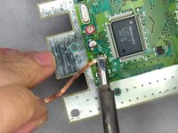
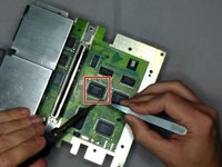
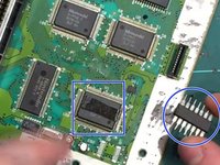
    • Remove the Lock Out chip (use the solder gun)

    • After removing the lock out chip there will probably be leftover of solder where the chip used to be so try to remove the soldier as good as you can

    • To remove the solder leftover, you can use the soldering iron and solder wick.

    Vraag FixBot

    Voeg opmerking toe

  8. SNES 2CHIP 50/60 Hz Switchless Mod + LED Mod, PPU 2: stap 8, afbeelding 1 van 2 SNES 2CHIP 50/60 Hz Switchless Mod + LED Mod, PPU 2: stap 8, afbeelding 2 van 2
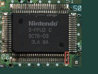
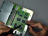
    • Lift up the PPU2 Pin 30 from the Motherboard

    Vraag FixBot

    Voeg opmerking toe

  9. SNES 2CHIP 50/60 Hz Switchless Mod + LED Mod, PPU 1: stap 9, afbeelding 1 van 2 SNES 2CHIP 50/60 Hz Switchless Mod + LED Mod, PPU 1: stap 9, afbeelding 2 van 2
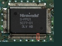
    • Now lift up Pin 24 on PPU 1

    Vraag FixBot

    Voeg opmerking toe

  10. SNES 2CHIP 50/60 Hz Switchless Mod + LED Mod, Wire Time: stap 10, afbeelding 1 van 1
    • Wire the lifted pins (PPU 2 Pin 30 & PPU1 Pin 24) together

    • You need to use a Soldering Iron to wire the pins together

    • You can also use tape to hold the wires down to the motherboard

    Vraag FixBot

    Voeg opmerking toe

  11. SNES 2CHIP 50/60 Hz Switchless Mod + LED Mod, Program: stap 11, afbeelding 1 van 1
    Vraag FixBot

    Voeg opmerking toe

  12. SNES 2CHIP 50/60 Hz Switchless Mod + LED Mod, The Pins: stap 12, afbeelding 1 van 3 SNES 2CHIP 50/60 Hz Switchless Mod + LED Mod, The Pins: stap 12, afbeelding 2 van 3 SNES 2CHIP 50/60 Hz Switchless Mod + LED Mod, The Pins: stap 12, afbeelding 3 van 3
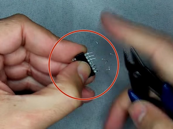
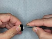
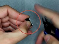
    • Bend the pins outwards

    • Then clip the pins

    • Use double sided tape and put it on top of the CPU and put the Super CIC on top of the double sided tape.

    Vraag FixBot

    Voeg opmerking toe

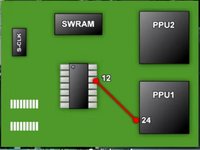
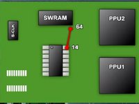
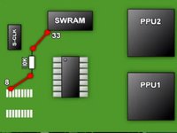
  13. SNES 2CHIP 50/60 Hz Switchless Mod + LED Mod, The Wires: stap 13, afbeelding 1 van 3 SNES 2CHIP 50/60 Hz Switchless Mod + LED Mod, The Wires: stap 13, afbeelding 2 van 3 SNES 2CHIP 50/60 Hz Switchless Mod + LED Mod, The Wires: stap 13, afbeelding 3 van 3
    • Pic 1: Solder a wire from Super CIC Pin 12 to PPU1 Pin 24

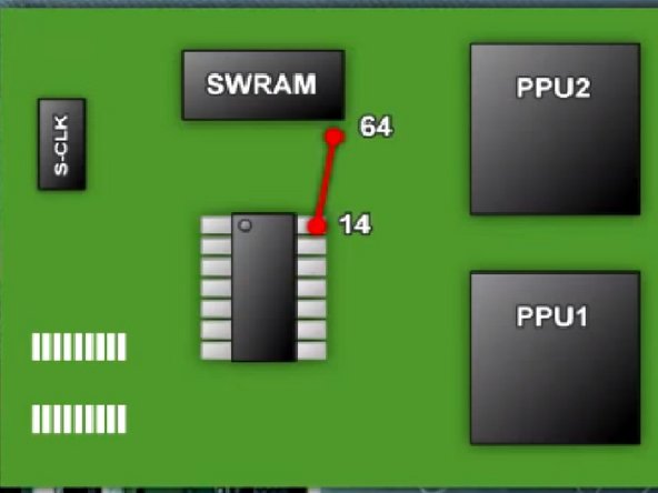
    • Pic 2: Solder a wire from Super CIC Pin 14 to SWRAM Pin 64

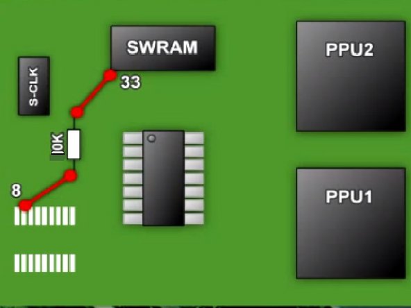
    • Pic 3: Solder the 10k Ohm Resistor to the pin 8 (where the old CIC used to be) and to SWRAM Pin 33

    Vraag FixBot

    Voeg opmerking toe

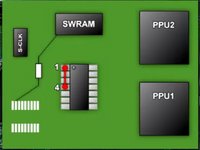
  14. SNES 2CHIP 50/60 Hz Switchless Mod + LED Mod, The Wires Part 2: stap 14, afbeelding 1 van 3 SNES 2CHIP 50/60 Hz Switchless Mod + LED Mod, The Wires Part 2: stap 14, afbeelding 2 van 3 SNES 2CHIP 50/60 Hz Switchless Mod + LED Mod, The Wires Part 2: stap 14, afbeelding 3 van 3
    • Pic 1: Solder a Wire from Super CIC Pin 1 to 4 on the same chip.

    • Pic 2: Solder a wire from Super CIC Pin 1 to the CPU Pin 1

    • Pic 3: Solder a wire from Super CIC Pin 13 to the End Point of the Resistor

    Vraag FixBot

    Voeg opmerking toe

  15. SNES 2CHIP 50/60 Hz Switchless Mod + LED Mod, The Wires Part 3: stap 15, afbeelding 1 van 3 SNES 2CHIP 50/60 Hz Switchless Mod + LED Mod, The Wires Part 3: stap 15, afbeelding 2 van 3 SNES 2CHIP 50/60 Hz Switchless Mod + LED Mod, The Wires Part 3: stap 15, afbeelding 3 van 3
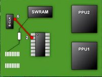
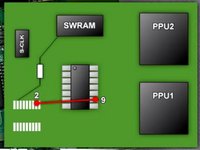
    • Pic 1: Sother a wire from Super CIC Pin 2 to S-CLK Pin 6

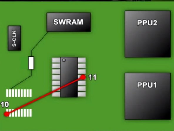
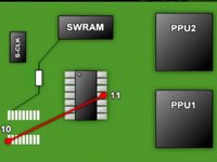
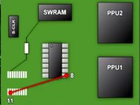
    • Pic 2: Sother a wire from Super CIC Pin 11 to Old CIC Pin 10

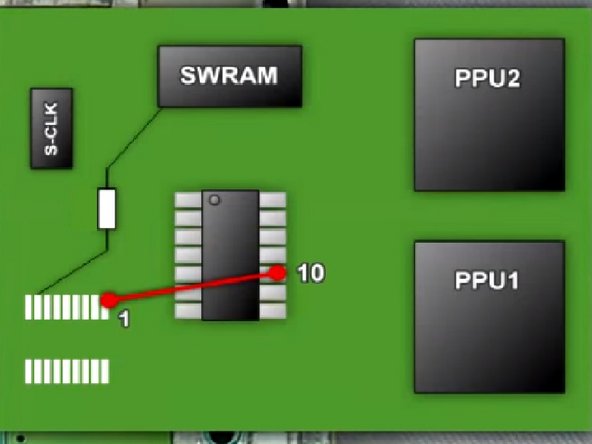
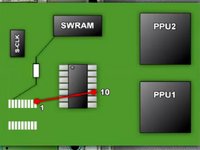
    • Pic 3: Sother a wire from Super CIC Pin 10 to Old CIC Pin 1

    Vraag FixBot

    Voeg opmerking toe

  16. SNES 2CHIP 50/60 Hz Switchless Mod + LED Mod, The Wires Part 4: stap 16, afbeelding 1 van 3 SNES 2CHIP 50/60 Hz Switchless Mod + LED Mod, The Wires Part 4: stap 16, afbeelding 2 van 3 SNES 2CHIP 50/60 Hz Switchless Mod + LED Mod, The Wires Part 4: stap 16, afbeelding 3 van 3
    • Pic 1: Solder a wire from Super CIC Pin 9 to Old CIC Pin 2

    • Pic 2: Solder a wire from Super CIC Pin 8 to Old CIC Pin 11

    • Pic 3: You've soldered most of the wires now, lets go to the LED Mod

    Vraag FixBot

    Voeg opmerking toe

  17. SNES 2CHIP 50/60 Hz Switchless Mod + LED Mod, The LED Mod: stap 17, afbeelding 1 van 3 SNES 2CHIP 50/60 Hz Switchless Mod + LED Mod, The LED Mod: stap 17, afbeelding 2 van 3 SNES 2CHIP 50/60 Hz Switchless Mod + LED Mod, The LED Mod: stap 17, afbeelding 3 van 3
    Gereedschap gebruikt in deze stap:
    Tweezers
    $4.99
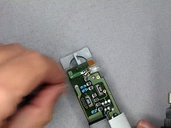
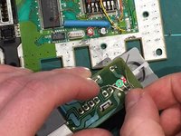
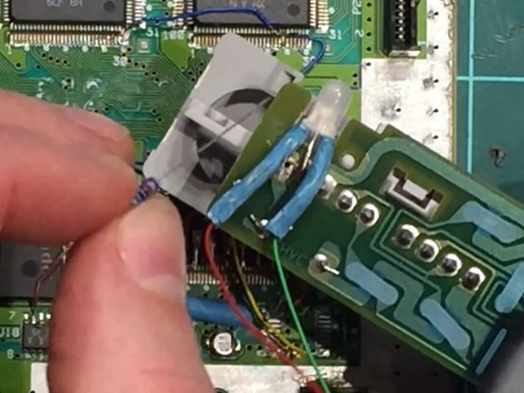
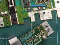
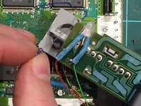
    • Plug out the controller ports and solder out the LED Light.

    • When the solder points have been desoldered, you can use the tweezers to pull out the led light

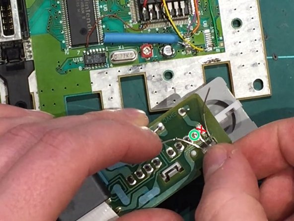
    • Sother on the new LED Light with the middle pin on the left solder hole

    • Do Not sother the middle pin on the LED Light to the right solder hole as it will then be stuck in only one color!

    Vraag FixBot

    Voeg opmerking toe

  18. SNES 2CHIP 50/60 Hz Switchless Mod + LED Mod, Led Resistors: stap 18, afbeelding 1 van 3 SNES 2CHIP 50/60 Hz Switchless Mod + LED Mod, Led Resistors: stap 18, afbeelding 2 van 3 SNES 2CHIP 50/60 Hz Switchless Mod + LED Mod, Led Resistors: stap 18, afbeelding 3 van 3
    • Solder 2 wires on the left and right pins on the led light, green wire on the left pin and red wire on the right pin.

    • After that you should put the wires into one heat shrink tube each, remember to heat the heat shrink tubes when its over the pins.

    • Then you have to solder the 2k Resistor to the red wire and the 220 ohm Resistor to the green wire.

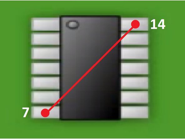
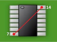
    • Then the last thing you need to do is to solder a wire from Super CIC Pin 7 to Pin 14.

    Vraag FixBot

    Voeg opmerking toe

  19. SNES 2CHIP 50/60 Hz Switchless Mod + LED Mod, The End: stap 19, afbeelding 1 van 3 SNES 2CHIP 50/60 Hz Switchless Mod + LED Mod, The End: stap 19, afbeelding 2 van 3 SNES 2CHIP 50/60 Hz Switchless Mod + LED Mod, The End: stap 19, afbeelding 3 van 3
    • You're Now Done! You just need to put your Super Nintendo back together and then you have a Region Free Switchless Super Nintendo!

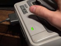
    • Green Light (PAL)

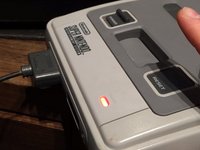
    • Red Light (NTSC) [For American and Japanese Games]

    • Orange Light (Auto)

    Vraag FixBot

    Voeg opmerking toe

Conclusie

To reassemble your device, follow these instructions in reverse order.

These screenshots have been taken by 2 videoes, one from Global Garage and Chips y Bits on YouTube! I made this guide since its a little easier to read a guide with pictures like this instead of watching a 30 min video

Annuleren: ik heb deze handleiding niet afgemaakt.

3 andere personen hebben deze handleiding voltooid.

Krisander 1998

Lid sinds: 10/18/17

668 Reputatie

2 handleidingen geschreven

3Gids Commentaar

Lo hice tal y como dice el tutorial y la snes se quedó con la pantalla negra.

dragonero - Antwoord Deel
Is there some way to get a chip that is already programmed? I don’t have a plan on doing this a lot and the $100 is a bit much at the moment.

Brandon Vanoni - Antwoord Deel
Will this same method be used for the PAL version if the console.

Adrees Sattar - Antwoord Deel

Voeg opmerking toe

Weergavestatistieken:

Afgelopen 24 uren: 3

Afgelopen 7 dagen: 27

Afgelopen 30 dagen: 164

Altijd: 21,622