Deze versie kan foutieve bewerkingen bevatten. Schakel over naar de recentste gecontroleerde momentopname.
Wat je nodig hebt
-
Deze stap is niet vertaald. Help het te vertalen
-
Use the plastic opening tool to carefully lift the rubber stops in each corner.
-
-
Deze stap is niet vertaald. Help het te vertalen
-
Unscrew the 4 11.8 mm T-8 Torx screws from each corner of the device.
-
-
Deze stap is niet vertaald. Help het te vertalen
-
Lift the lower case straight up from the rest of the router.
-
-
-
Deze stap is niet vertaald. Help het te vertalen
-
Remove the clear plastic casing by lifting it straight up from the router.
-
-
Deze stap is niet vertaald. Help het te vertalen
-
Separate the motherboard from the top shell by lifting it straight up from the router.
-
-
Deze stap is niet vertaald. Help het te vertalen
-
Turn the motherboard so that the top is facing upwards.
-
Place the motherboard on a clean flat surface.
-
-
Deze stap is niet vertaald. Help het te vertalen
-
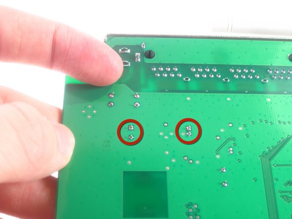
Turn the motherboard so that the bottom is facing upwards.
-
Locate the two soldered contacts for each capacitor.
-
-
Deze stap is niet vertaald. Help het te vertalen
-
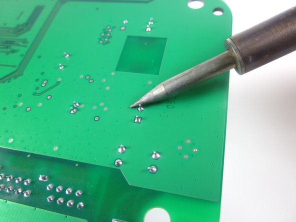
Desolder the soldered connections between the capacitors and the motherboard, and pull the capacitor from the motherboard.
-


Annuleren: ik heb deze handleiding niet afgemaakt.
Één andere persoon heeft deze handleiding voltooid.

Team

Cal Poly, Team 3-31, Amido Winter 2013 Lid van Cal Poly, Team 3-31, Amido Winter 2013
CPSU-AMIDO-W13S3G31
3 Leden
12 handleidingen geschreven
Één opmerking
my router NETGEAR WNR 612 WIFI LED NOT GLOWING PLEASE HLP ME IN REPAIRING