Deze versie kan foutieve bewerkingen bevatten. Schakel over naar de recentste gecontroleerde momentopname.
Wat je nodig hebt
-
Deze stap is niet vertaald. Help het te vertalen
-
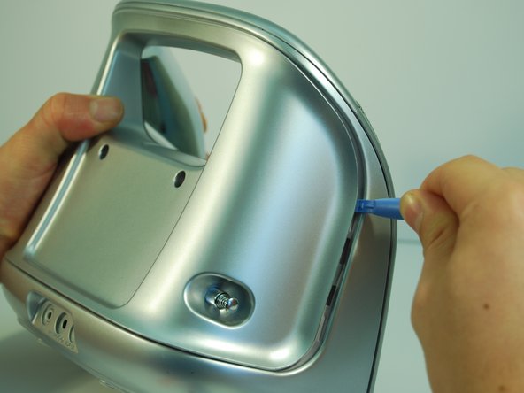
Remove the two plastic screw covers on the back of your Minimove by inserting the flat end of your plastic opening tool between the screw cover and the back panel and prying it out.
-
-
Deze stap is niet vertaald. Help het te vertalen
-
Use a Phillips #1 screwdriver to remove the two 12 mm screws.
-
-
Deze stap is niet vertaald. Help het te vertalen
-
Remove the four grey screw covers by inserting the plastic opening tool underneath the screw covers and rotating around the circumference.
-
-
Deze stap is niet vertaald. Help het te vertalen
-
Remove the two 8 mm screws with a Phillips #1 screwdriver.
-
Remove the two 12 mm screws with a long Phillips #1 screwdriver.
-
-
Deze stap is niet vertaald. Help het te vertalen
-
To remove the back panel, use the plastic opening tool and gently work around the outline of the panel. The outline wraps around the sides and can be spotted at the top back of the device.
-
-
Deze stap is niet vertaald. Help het te vertalen
-
After loosening the panel with the plastic opening tool, use moderate force to pry open the panel with your hands.
-
Carefully pull the panel off.
-
-
-
Deze stap is niet vertaald. Help het te vertalen
-
Use a Phillips #1 screwdriver to detach the wire from the back panel by removing the 8 mm screw connecting the wire to the antenna.
-
-
Deze stap is niet vertaald. Help het te vertalen
-
If desired, the antenna can now be removed by pulling inwards and horizontal to the panel bottom.
-
-
Deze stap is niet vertaald. Help het te vertalen
-
Use the Phillips #1 screwdriver to remove the four 12 mm screws.
-
Remove the five 6 mm screws at the top with the same screwdriver.
-
-
Deze stap is niet vertaald. Help het te vertalen
-
Use a Phillips #1 screwdriver and remove the two vertical 8 mm screws from the top.
-
-
Deze stap is niet vertaald. Help het te vertalen
-
Pry open the inner back panel by inserting the plastic opening tool in the crack at the top corner.
-
Use moderate force to pry it open and take the cover off.
-
-
Deze stap is niet vertaald. Help het te vertalen
-
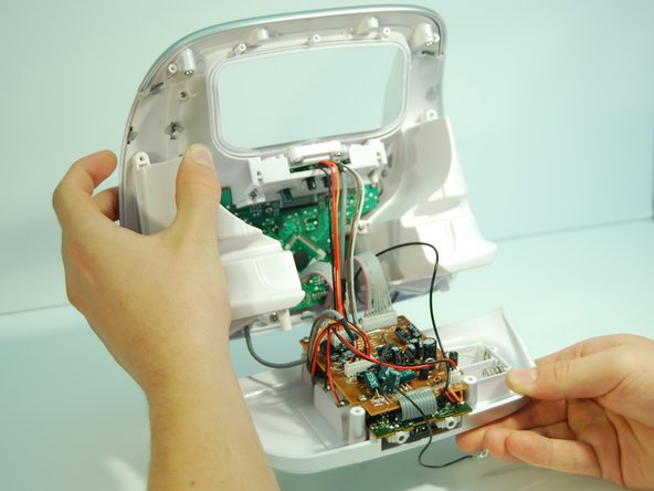
Remove the bottom panel of the boombox by carefully pulling the panel straight backwards from the boombox until the boards are free.
-
-
Deze stap is niet vertaald. Help het te vertalen
-
Pull out the 5 white pinhead connectors using an IC (Integrated Circuit) extractor. Pinch the IC extractor just under the top lip of the wire housing. There are two 10 pin connectors, one 8 pin connector, one 7 pin connector, and one 2 pin connector.
-
-
Deze stap is niet vertaald. Help het te vertalen
-
Use the Phillips #1 screwdriver to remove the three 8 mm screws holding the motherboard in place.
-
-
Deze stap is niet vertaald. Help het te vertalen
-
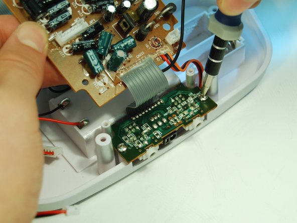
Detach the smaller green audio port daughterboard by removing the two 8 mm screws with a Phillips #1 screwdriver.
-
-
Deze stap is niet vertaald. Help het te vertalen
-
Detach the black ground wire by desoldering it from the inner case.
-
Visit the soldering guide for help with desoldering.
-


Annuleren: ik heb deze handleiding niet afgemaakt.
2 andere personen hebben deze handleiding voltooid.
Team

Cal Poly, Team 2-9, Amido Winter 2014 Lid van Cal Poly, Team 2-9, Amido Winter 2014
CPSU-AMIDO-W14S2G9
5 Leden
6 handleidingen geschreven