Deze versie kan foutieve bewerkingen bevatten. Schakel over naar de recentste gecontroleerde momentopname.
Wat je nodig hebt
-
-
Verwijder de volgende tien schroeven die de onderste behuizing aan de bovenste behuizing bevestigen:
-
Drie 13.5 mm (14.1 mm) lange Phillips schroeven.
-
Zeven 3 mm lange Phillips schroeven.
-
-
-
Verwijder de twee 7.4 mm lange Tri-point schroeven die de batterij aan de bovenste behuizing bevestigen.
-
Let op: voor sommige reparaties (eg. harde schijf) is het niet noodzakelijk de batterij te verwijderen. Toch wordt het altijd aangeraden aangezien je hiermee voorkomt dat je apparaat per ongeluk kortsluiting maakt op het moederbord. Wees, als je de batterij niet verwijdert, voorzichtig aangezien sommige delen van het moederbord geladen kunnen zijn.
-
-
-
Kantel de batterij ver genoeg van het logic board weg om zo toegang te krijgen tot de kabelaansluiting van de batterij.
-
Trek de kabelaansluiting van de batterij weg van het contact op het logic board en verwijder de batterij uit de bovenste behuizing.
-
Laad deze op tot 100% en laat 'm nog minstens twee uur doorladen. Gebruik je apparaat vervolgens totdat deze uitvalt vanwege een lege batterij. Wacht minstens 5 uur en laad je batterij tot slot nog een keer ononderbroken op tot 100%.
-
Als je vreemd gedrag of problemen tegenkomt na het installeren van je nieuwe batterij kan het handig zijn om de SMC van je MacBook te resetten.
-
-
Deze stap is niet vertaald. Help het te vertalen
-
Remove the three 3.4 mm T6 Torx screws securing the left fan to the logic board.
-
-
Deze stap is niet vertaald. Help het te vertalen
-
Use the flat end of a spudger to disconnect the left fan connector from the logic board.
-
-
-
Deze stap is niet vertaald. Help het te vertalen
-
Remove the three T6 Torx screws securing the right fan to the upper case.
-
-
Deze stap is niet vertaald. Help het te vertalen
-
Use the flat end of a spudger to pry the right fan connector up out of its socket on the logic board.
-
Remove the right fan from the upper case.
-
-
Deze stap is niet vertaald. Help het te vertalen
-
Use the flat end of a spudger to pry the AirPort / Bluetooth ribbon cable up off its socket on the logic board.
-
-
Deze stap is niet vertaald. Help het te vertalen
-
Disconnect the iSight cable by pulling its connector toward the optical drive opening.
-
-
Deze stap is niet vertaald. Help het te vertalen
-
Use the flat end of a spudger to pry the optical drive cable connector up from the logic board.
-
-
Deze stap is niet vertaald. Help het te vertalen
-
Carefully pull the subwoofer/right speaker cable up to lift its connector out of its socket on the logic board.
-
-
Deze stap is niet vertaald. Help het te vertalen
-
Use the flat end of a spudger to pry the hard drive cable connector up out of its socket on the logic board.
-
-
Deze stap is niet vertaald. Help het te vertalen
-
Remove the two short Phillips screws securing the small EMI shield to the logic board.
-
Remove the EMI shield from the logic board.
-
-
Deze stap is niet vertaald. Help het te vertalen
-
Use the flat end of a spudger to pry the trackpad cable connector up out of its socket on the logic board.
-
-
Deze stap is niet vertaald. Help het te vertalen
-
Use your fingernail to carefully flip up the keyboard ribbon cable retaining flap.
-
Use the tip of a spudger to pull the keyboard ribbon cable straight out of its socket.
-
-
Deze stap is niet vertaald. Help het te vertalen
-
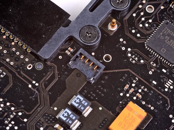
Use the flat end of a spudger to pry the battery indicator cable connector up out of its socket on the logic board.
-
-
Deze stap is niet vertaald. Help het te vertalen
-
Grab the plastic pull tab secured to the display data cable lock and rotate it toward the DC-In side of the computer.
-
Pull the display data cable straight out of its socket.
-
-
Deze stap is niet vertaald. Help het te vertalen
-
Use the tip of a spudger or your fingernail to flip up the retaining flap on the keyboard backlight ribbon cable socket.
-
Pull the keyboard ribbon cable straight out of its socket.
-
-
Deze stap is niet vertaald. Help het te vertalen
-
Remove the following screws:
-
Seven 3.3 mm T6 Torx screws securing the logic board to the upper case.
-
Two 8 mm T6 Torx screws securing the DC-In board to the upper case.
-
-
Deze stap is niet vertaald. Help het te vertalen
-
Carefully lift the logic board assembly from the left side and work it out of the upper case, minding the port side that may get caught during removal.
-
-
Deze stap is niet vertaald. Help het te vertalen
-
Lift the logic board enough to gain clearance and use a spudger to pry the microphone up off the upper case.
-
-
Deze stap is niet vertaald. Help het te vertalen
-
Slide the logic board away from the port openings and lift the assembly out of the upper case.
-
-
Deze stap is niet vertaald. Help het te vertalen
-
Disconnect the DC-In board by pulling its cable toward the heat sink.
-


Annuleren: ik heb deze handleiding niet afgemaakt.
65 andere personen hebben deze handleiding voltooid.

4 opmerkingen
Excellent walkthrough! This was my first ifixit repair and I was able to successfully replace my damaged magsafe board. The 64-Bit driver kit was the perfect companion to this project and the many more that will come in the future.
Thanks for your help! I think something on the mainboard is toast and the computer is a total loss, but it was worth it to take a chance and see if the cheap mag board would fix it. Good guide!
Good guide - gave me the confidence to have a go - thanks - I would say to others be very gentle with the cable connectors - mine weren’t exactly the same type as shown in the guide - be patient and you’ll work it out.
I did the same procedure yesterday replacing a malfunction on magsafe board, just before signing up for Fixit and viewing this document. The walkthrough depicted here is really detailed and very well done. Excellent.