Deze versie kan foutieve bewerkingen bevatten. Schakel over naar de recentste gecontroleerde momentopname.
Wat je nodig hebt
-
-
Verwijder de volgende tien schroeven die de onderste behuizing aan de bovenste behuizing bevestigen:
-
Drie 13.5 mm (14.1 mm) lange Phillips schroeven.
-
Zeven 3 mm lange Phillips schroeven.
-
-
-
Gebruik de platte kant van een spudger om de batterijaansluiting uit het contact op het logic board omhoog te duwen.
-
-
-
Verwijder de twee 7.4 mm lange Tri-point schroeven die de batterij aan de bovenste behuizing bevestigen.
-
-
-
Gebruik de al geïnstalleerde plasticen treklip om de batterij uit de bovenste behuizing te verwijderen.
-
Laat je batterij op tot 100% en laat deze nog minstens twee uur doorladen. Gebruik je apparaat vervolgens totdat deze zichzelf uitschakelt vanwege een lege batterij. Wacht dan minstens 5 uur en laad je batterij tot slot nog een keer ononderbroken op tot 100%.
-
Als je onverwachts gedrag of problemen tegenkomt na het installeren van je batterij kan het nodig zijn dat je de SMC van je MacBook moet resetten.
-
-
Deze stap is niet vertaald. Help het te vertalen
-
Remove the three 3.4 mm T6 Torx screws securing the left fan to the logic board.
-
-
Deze stap is niet vertaald. Help het te vertalen
-
Use the flat end of a spudger to disconnect the left fan connector from the logic board.
-
-
Deze stap is niet vertaald. Help het te vertalen
-
Use the flat end of a spudger to lift the right fan connector out of its socket on the logic board.
-
-
-
Deze stap is niet vertaald. Help het te vertalen
-
Remove the three 3.4 mm (3.1 mm) T6 Torx screws securing the right fan to the logic board.
-
Lift the right fan out of its opening in the logic board.
-
-
Deze stap is niet vertaald. Help het te vertalen
-
Pull the camera cable out of its socket on the logic board.
-
-
Deze stap is niet vertaald. Help het te vertalen
-
Use the flat end of a spudger to pry the AirPort/Bluetooth connector up from its socket on the logic board.
-
-
Deze stap is niet vertaald. Help het te vertalen
-
Use the flat end of a spudger to lift the optical drive connector out of its socket on the logic board.
-
-
Deze stap is niet vertaald. Help het te vertalen
-
Disconnect the hard drive/IR sensor cable from its socket on the logic board by lifting up from beneath its connector.
-
-
Deze stap is niet vertaald. Help het te vertalen
-
Use the flat end of a spudger to lift the subwoofer/right speaker connector out of its socket on the logic board.
-
-
Deze stap is niet vertaald. Help het te vertalen
-
Remove the two 1.5 mm ( 1.2 mm ) Phillips screws securing the keyboard/trackpad cable cover to the logic board.
-
Lift the cover off the logic board and set it aside.
-
-
Deze stap is niet vertaald. Help het te vertalen
-
Use the flat end of a spudger to pry the trackpad connector up and out of its socket on the logic board.
-
-
Deze stap is niet vertaald. Help het te vertalen
-
Use your fingernail to flip up the retaining flap on the keyboard ribbon cable ZIF socket.
-
Use the tip of a spudger to pull the keyboard ribbon cable out of its socket.
-
-
Deze stap is niet vertaald. Help het te vertalen
-
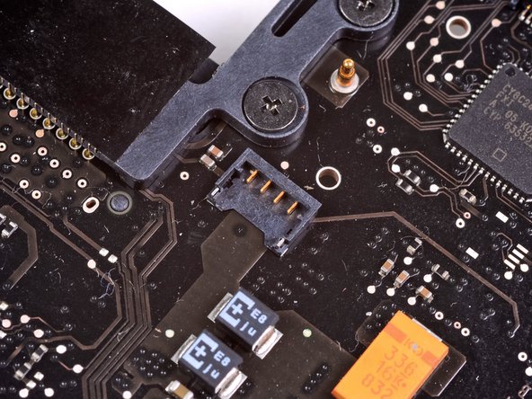
Use the flat end of a spudger to lift the battery indicator connector up and out of its socket on the logic board.
-
-
Deze stap is niet vertaald. Help het te vertalen
-
Grab the plastic pull tab secured to the display data cable lock and rotate it toward the DC-In side of the computer.
-
Pull the display data cable straight out of its socket on the logic board.
-
-
Deze stap is niet vertaald. Help het te vertalen
-
Use the tip of a spudger to flip up the retaining flap on the keyboard backlight ribbon cable ZIF socket.
-
Pull the keyboard backlight ribbon cable out of its socket.
-
-
Deze stap is niet vertaald. Help het te vertalen
-
Remove the following nine screws:
-
Seven 3.4 mm ( 3.1 mm) T6 Torx screws on the logic board
-
Two 8 mm T6 Torx screws on the DC-In board
-
-
Deze stap is niet vertaald. Help het te vertalen
-
Carefully lift the logic board assembly from its left side and work it out of the upper case, minding the optical drive cable and the I/O ports that may get caught during removal.
-
If necessary, use the flat end of a spudger to separate the microphone from the upper case.
-
Pull the I/O port side of the logic board away from the side of the upper case and remove the logic board assembly.
-
-
Deze stap is niet vertaald. Help het te vertalen
-
Remove the six #1 Phillips screws securing the heat sink to the logic board.
-
-
Deze stap is niet vertaald. Help het te vertalen
-
Remove the two 5 mm Phillips screws securing the left speaker to the logic board.
-
-
Deze stap is niet vertaald. Help het te vertalen
-
Carefully pull the left speaker wires upward to lift the left speaker connector out of its socket on the logic board.
-
-
Deze stap is niet vertaald. Help het te vertalen
-
Carefully pull the microphone cables upward to lift the microphone connector out of its socket on the logic board.
-
-
Deze stap is niet vertaald. Help het te vertalen
-
Pull the DC-In board cables toward the heat sink to disconnect the DC-In board from its socket on the logic board.
-
-
Deze stap is niet vertaald. Help het te vertalen
-
Release the tabs on each side of the RAM chip by simultaneously pushing each tab away from the RAM.
-
After the RAM chip has popped up, pull it straight out of its socket.
-
Logic board remains.
-
If you need to mount the heat sink back onto the logic board, we have a thermal paste guide that makes replacing the thermal compound easy.
-


Annuleren: ik heb deze handleiding niet afgemaakt.
72 andere personen hebben deze handleiding voltooid.

11 opmerkingen
i need the screws which go on the lid of the back of the mac what are those screws called and how much they are i really really need them my mac screws have all been removed ever since i changed hdd and i need screws for the back lid lower case to upper case screws
Does anyone ever respond to these post? Why come here for help if no is here to help?
Thank you Miroslav! My computer blew up last week and I felt all hope was lost until I found your guide. I used to repair laptops 10 years ago but never worked on a mac. this is exactly what I needed to see to know what to do!
Apple had a replacement service for late 2011 15inch MBPs which cured a mysterious fault which rendered it un-usable. I had mine fixed at a Genius Bar but my mate who also bought one has missed the program and has a completely dead MBP. Am I right in assuming that following your procedure above and using one of your logic boards would fix this?