Deze versie kan foutieve bewerkingen bevatten. Schakel over naar de recentste gecontroleerde momentopname.
Wat je nodig hebt
-
-
Verwijder de volgende tien schroeven die de onderste behuizing aan de bovenste behuizing bevestigen:
-
Zeven 3 mm lange Phillips schroeven.
-
Drie 13.5 mm lange Phillips schroeven.
-
-
-
Drie Pentalobe schroeven bevestigen de batterij aan de bovenste behuizing. Deze kunnen worden verwijderd met deze speciale schroevendraaier.
-
-
Deze stap is niet vertaald. Help het te vertalen
-
Use the flat end of a spudger to pry the fan cable connector up off its socket on the logic board.
-
-
Deze stap is niet vertaald. Help het te vertalen
-
Remove the three identical T6 Torx screws securing the fan to the upper case.
-
-
Deze stap is niet vertaald. Help het te vertalen
-
Hold the end of the cable retainer down with one finger while you use the tip of a spudger to slightly lift the other end and rotate it away from the camera cable connector.
-
-
Deze stap is niet vertaald. Help het te vertalen
-
Disconnect the camera cable by pulling the male end straight away from its socket.
-
-
Deze stap is niet vertaald. Help het te vertalen
-
Use the flat end of a spudger to pry the optical drive cable connector up off the logic board.
-
-
-
Deze stap is niet vertaald. Help het te vertalen
-
Using the flat end of a spudger, pry the subwoofer connector straight up off the logic board.
-
-
Deze stap is niet vertaald. Help het te vertalen
-
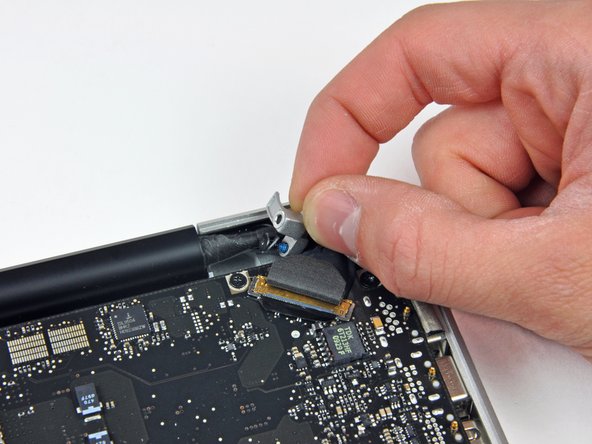
Use the flat end of a spudger to pry the hard drive/IR sensor cable connector up off the logic board.
-
-
Deze stap is niet vertaald. Help het te vertalen
-
Remove the two 1.5 mm Phillips screws securing the cable cover to the logic board.
-
Lift the cable cover out of the upper case.
-
-
Deze stap is niet vertaald. Help het te vertalen
-
Use a spudger to pry the trackpad flex ribbon cable connector up off the logic board.
-
-
Deze stap is niet vertaald. Help het te vertalen
-
Using the tip of a spudger, flip up the keyboard ribbon cable retaining flap.
-
Pull the keyboard ribbon cable straight out of its socket.
-
-
Deze stap is niet vertaald. Help het te vertalen
-
Use a spudger to pry the battery indicator ribbon cable connector up off the logic board.
-
-
Deze stap is niet vertaald. Help het te vertalen
-
Remove the single 7 mm Phillips screw securing the display data cable retainer to the upper case.
-
Remove the display data cable retainer from the upper case.
-
-
Deze stap is niet vertaald. Help het te vertalen
-
Grab the plastic pull tab secured to the display data cable lock and rotate it toward the DC-in side of the computer.
-
Pull the display data cable connector straight away from its socket.
-
-
Deze stap is niet vertaald. Help het te vertalen
-
Using the tip of a spudger, flip up the keyboard backlight ribbon cable retaining flap.
-
Pull the keyboard backlight ribbon cable straight out of its socket.
-
-
Deze stap is niet vertaald. Help het te vertalen
-
Remove the following screws:
-
Eight 3.5 mm T6 Torx screws securing the logic board to the upper case.
-
Two T6 Torx screws securing the DC-In board to the upper case.
-
-
Deze stap is niet vertaald. Help het te vertalen
-
Carefully lift the logic board assembly from the left side and work it out of the upper case, minding the port side that may get caught during removal.
-
-
Deze stap is niet vertaald. Help het te vertalen
-
Lift the logic board enough to gain clearance and use a spudger to pry the microphone up off the upper case.
-
Slide the logic board away from the port openings and lift the assembly out of the upper case.
-
-
Deze stap is niet vertaald. Help het te vertalen
-
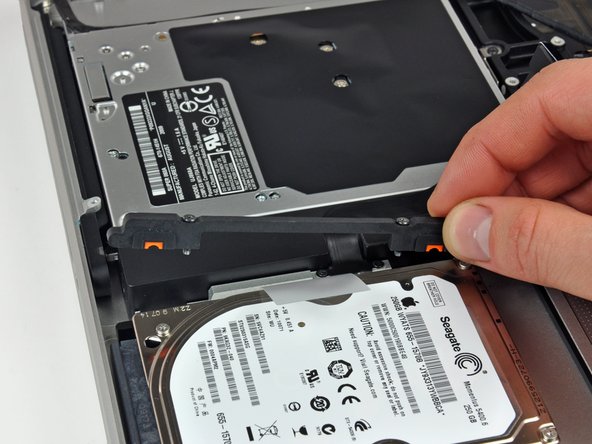
Remove the two Phillips screws securing the hard drive bracket to the upper case.
-
Remove the hard drive bracket from the upper case.
-
-
Deze stap is niet vertaald. Help het te vertalen
-
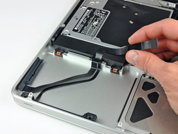
Lift the hard drive out of the upper case by its plastic pull tab, minding the cable attaching it to the computer.
-
-
Deze stap is niet vertaald. Help het te vertalen
-
Remove the hard drive from its cable by pulling the cable connector straight away from the drive.
-
-
Deze stap is niet vertaald. Help het te vertalen
-
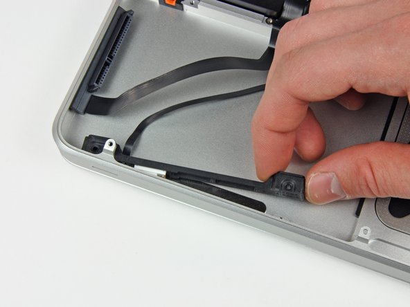
Remove the following four screws securing the hard drive and IR sensor cable to the upper case:
-
Two 1.5 mm Phillips screws.
-
Two 4 mm Phillips screws.
-
Slide the hard drive and IR sensor bracket away from the edge of the upper case.
-
Carefully peel the hard drive and IR sensor cable from the upper case.
-
Remove the hard drive/IR sensor cable from the upper case and set it aside.
-
-
Deze stap is niet vertaald. Help het te vertalen
-
Peel the camera cable off the adhesive securing it to the optical drive.
-
-
Deze stap is niet vertaald. Help het te vertalen
-
Remove the three 3.5 mm Phillips screws securing the optical drive to the upper case.
-
Lift the optical drive from its left edge and pull it out of the computer.
-
-
Deze stap is niet vertaald. Help het te vertalen
-
Remove the following four screws securing the subwoofer and right speaker to the upper case:
-
Two 3.2 mm Phillips screws.
-
One 2.6 mm Phillips screw.
-
One 5 mm Phillips screw.
-
Lift the subwoofer and right speaker assembly out of the upper case.
-
-
Deze stap is niet vertaald. Help het te vertalen
-
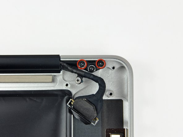
Remove the two 8 mm Phillips screws securing the camera cable retainer to the upper case.
-
Lift the camera cable retainer out of the upper case.
-
-
Deze stap is niet vertaald. Help het te vertalen
-
Remove two outer 6 mm Torx screws securing each side of the display to the upper case (4 screws total).
-
-
Deze stap is niet vertaald. Help het te vertalen
-
Open your MacBook Pro so the display is perpendicular to the upper case.
-
Place your opened MacBook Pro on a table as pictured.
-
While holding the display and upper case together with your other hand, remove the 6 mm Torx screw from the lower display bracket.
-
-
Deze stap is niet vertaald. Help het te vertalen
-
Remove the last remaining 6 mm Torx screw securing the display to the upper case.
-
-
Deze stap is niet vertaald. Help het te vertalen
-
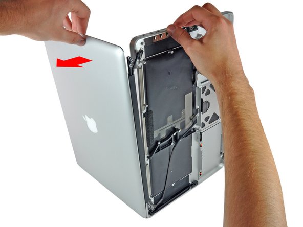
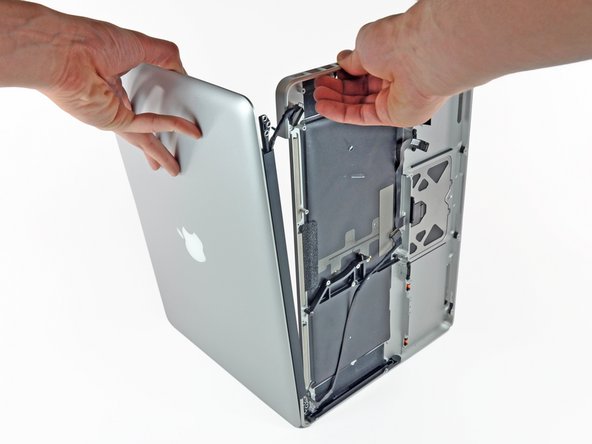
Grab the upper case with your right hand and rotate it slightly toward the top of the display so the upper display bracket clears the edge of the upper case.
-
Rotate the display slightly away from the upper case.
-
Lift the display away from the upper case, minding any brackets or cables that may get caught.
-


Annuleren: ik heb deze handleiding niet afgemaakt.
21 andere personen hebben deze handleiding voltooid.

Één opmerking
This is a good guide. I got to this point and started to unscrew the screws holding the top case to the display however the T6 spun and I think I may have ruined a couple of the screws. A T7 didn't fit - too big.
Do you have any ideas on a) which type of screwdriver should fit or do you think by T6 is just poor quality and b) what to do about the screws that are now going to be impossible to take out - not sure I want to be drilling them out.