Ga door naar hoofdinhoud

Deze versie kan foutieve bewerkingen bevatten. Schakel over naar de recentste gecontroleerde momentopname.

Wat je nodig hebt

  1. , Onderste behuizing: stap 1, afbeelding 1 van 1
    • Verwijder de volgende tien schroeven die de onderste behuizing aan de bovenste behuizing bevestigen:

    • Zeven 3 mm lange Phillips schroeven.

    • Drie 13.5 mm lange Phillips schroeven.

  2. : stap 2, afbeelding 1 van 1
    • Til de onderste behuizing, met beide handen, omhoog vanaf ongeveer de ventilatieopening om deze zodoende vrij te maken uit de twee klemmen die de behuizing aan de bovenste behuizing bevestigen.

    • Verwijder de onderste behuizing en leg deze weg.

  3. , Batterij: stap 3, afbeelding 1 van 1
    Gereedschap gebruikt in deze stap:
    P6 Pentalobe Screwdriver 2009 15" MacBook Pro Battery
    $5.49
    Koop
    • Drie Pentalobe schroeven bevestigen de batterij aan de bovenste behuizing. Deze kunnen worden verwijderd met deze speciale schroevendraaier.

    • Als je geen Pentalobe-schroevendraaier hebt, kun je als alternatief ook een 1.5 mm brede platkopschroevendraaier gebruiken. Zorg hierbij dat het einde van je platkopschroevendraaier precies in twee van de vijf punten van de schroef past voordat je begint met schroeven, aangezien je anders het risico loopt de schroef door te draaien.

    • Als je schroevendraaier niet helemaal past, zorg je dat je een maatje groter pakt en deze vijlt totdat deze vrijwel precies past.

    • Je hoeft de stappen 3-7, die laten zien hoe je de batterij verwijdert, niet per se te volgen om de harde schijf te vervangen. Echter, het wordt altijd aangeraden om alle stroombronnen van een apparaat te verwijderen voordat je begint met enige reparatie.

  4. : stap 4, afbeelding 1 van 1
    • Verwijder de twee vijfpunts-Pentalobe schroeven langs de bovenkant van de batterij.

  5. : stap 5, afbeelding 1 van 1
    • Gebruik de punt van een spudger om de vinger van de sticker met "Warning: Do not remove the battery" naar achteren te buigen, zodat je de vijfpunts-Pentalobe schroef eronder kunt verwijderen.

  6. : stap 6, afbeelding 1 van 2 : stap 6, afbeelding 2 van 2
    • Til de batterij door middel van de plastic treklip omhoog en schuif deze weg van de lange kant van de bovenste behuizing.

    • Probeer de batterij nog niet volledig te verwijderen.

  7. : stap 7, afbeelding 1 van 1
    • Kantel de batterij ver genoeg naar achteren om de kabelaansluiting van de batterij te kunnen bereiken.

    • Trek de kabelaansluiting van de batterij weg uit het contact op het logic board en verwijder de batterij vervolgens uit de bovenste behuizing.

    • Zorg dat je, als je een nieuwe batterij installeert, je nieuwe batterij ook kalibreert!

  8. Deze stap is niet vertaald. Help het te vertalen

    : stap 8, afbeelding 1 van 2 : stap 8, afbeelding 2 van 2
    • Apple sticks a small strip of clear plastic with adhesive applied to one side to the logic board behind the camera cable connector to keep it in its socket. When moving it out of the way, be sure not to break any surface-mount components off the logic board.

    • Hold the end of the cable retainer down with one finger while you use the tip of a spudger to slightly lift the other end and rotate it away from the camera cable connector.

    • Pull the camera cable away from its socket on the logic board.

    • Pull the connector parallel to the face of the logic board, not straight up.

  9. Deze stap is niet vertaald. Help het te vertalen

    : stap 9, afbeelding 1 van 1
    • Peel the camera cable off the adhesive securing it to the optical drive.

  10. Deze stap is niet vertaald. Help het te vertalen

    : stap 10, afbeelding 1 van 2 : stap 10, afbeelding 2 van 2
    • This step is only required if you have an anti-glare display. If you have a glossy display, skip to step 12.

    • Disconnect the Bluetooth cable by pulling the male end straight away from its socket.

    • Pull the connector parallel to the face of the logic board, not straight up.

    • Use the flat end of a spudger to pry the Bluetooth antenna cable from its socket on the board.

  11. Deze stap is niet vertaald. Help het te vertalen

    : stap 11, afbeelding 1 van 2 : stap 11, afbeelding 2 van 2
    • This step is only required if you have an anti-glare display.

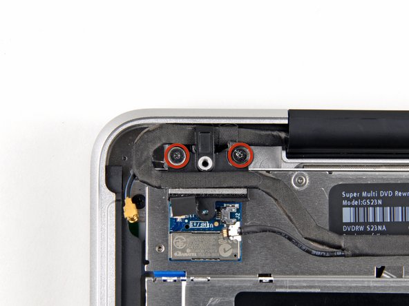
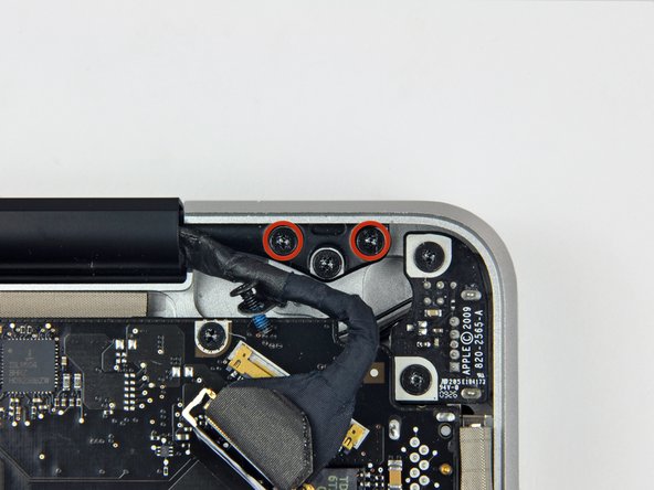
    • Remove the two 8 mm Phillips screws securing the Bluetooth/camera cable retainer to the upper case.

    • One of the screws may remain captive in the Bluetooth/camera cable ground loop. If replacing the display, be sure to transfer this screw to the new unit.

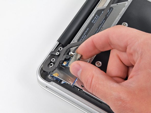
    • Lift the Bluetooth board/cable retainer assembly out of the upper case.

  12. Deze stap is niet vertaald. Help het te vertalen

    : stap 12, afbeelding 1 van 2 : stap 12, afbeelding 2 van 2
    • This step is only for glossy display machines. If you have an anti-glare display, skip this step.

    • Remove the two 8 mm Phillips screws securing the camera cable retainer to the upper case.

    • One of the screws may remain captive in the camera cable ground loop. If replacing the display, be sure to transfer this screw to the new unit.

    • Lift the camera cable retainer out of the upper case.

  13. Deze stap is niet vertaald. Help het te vertalen

    : stap 13, afbeelding 1 van 2 : stap 13, afbeelding 2 van 2
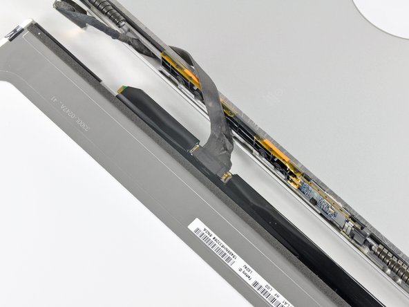
    • Remove the single 7 mm Phillips screw securing the display data cable retainer to the upper case.

    • This screw may remain captive in the display data cable ground loop. If replacing the display, be sure to transfer this screw to the new unit.

    • Remove the display data cable retainer from the upper case.

  14. Deze stap is niet vertaald. Help het te vertalen

    : stap 14, afbeelding 1 van 2 : stap 14, afbeelding 2 van 2
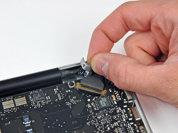
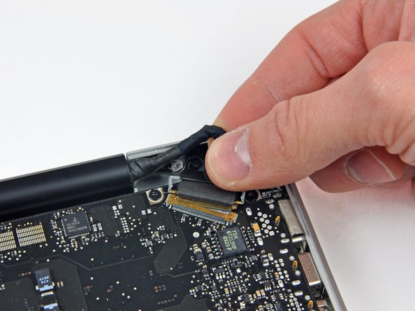
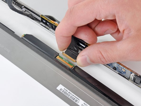
    • Grab the plastic pull tab secured to the display data cable lock and rotate it toward the DC-in side of the computer.

    • Pull the display data cable connector straight away from its socket.

    • Make sure to pull the connector parallel to the face of the logic board, not straight up from its socket.

  15. Deze stap is niet vertaald. Help het te vertalen

    : stap 15, afbeelding 1 van 2 : stap 15, afbeelding 2 van 2
    • Remove the outer two T6 Torx screws securing both display hinges to the upper case (four screws total).

  16. Deze stap is niet vertaald. Help het te vertalen

    : stap 16, afbeelding 1 van 1
    • Open your MacBook so the display is perpendicular to the upper case.

    • Place your opened MacBook on a table as pictured.

    • While holding the display and upper case together with your left hand, remove the remaining 6.5 mm Torx screw from the lower display bracket.

  17. Deze stap is niet vertaald. Help het te vertalen

    : stap 17, afbeelding 1 van 1
    • Be sure to hold the display and upper case together with your left hand. Failure to do so may cause the freed display/upper case to fall, potentially damaging each component.

    • Remove the last remaining 6 mm T6 Torx screw securing the display to the upper case.

  18. Deze stap is niet vertaald. Help het te vertalen

    : stap 18, afbeelding 1 van 3 : stap 18, afbeelding 2 van 3 : stap 18, afbeelding 3 van 3
    • Grab the upper case with your right hand and rotate it slightly toward the top of the display so the upper display bracket clears the edge of the upper case.

    • Rotate the display slightly away from the upper case.

    • Lift the display up and away from the upper case, minding any brackets or cables that may get caught.

  19. Deze stap is niet vertaald. Help het te vertalen

    : stap 19, afbeelding 1 van 2 : stap 19, afbeelding 2 van 2
    • In the following steps, you will use a heat gun to soften the adhesive securing the outer black border around the underside of the front glass panel to the display. The area the adhesive is applied to is shown in red in the second picture.

    • Before starting, be sure to clean the display glass with lint-free cloth moistened with a mild solution; it will make the suction cup adhere better, and will make checking for dust on reassembly easier

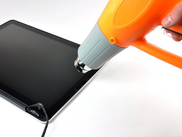
    • With the heat gun set to low, start by heating the outer black border near the upper right corner of the glass panel.

    • Always aim the heat gun away from the soft rubber strip around the display glass. Heating the rubber will cause it to melt slightly, turning its finish from matte to glossy. Touching overheated rubber can cause it to permanently deform.

    • Due to the heat applied, it is normal for a layer of condensation to develop on the inside of the glass panel and/or the outside of the LCD. It can be removed with glass cleaner once the glass is separated from the display.

  20. Deze stap is niet vertaald. Help het te vertalen

    : stap 20, afbeelding 1 van 3 : stap 20, afbeelding 2 van 3 : stap 20, afbeelding 3 van 3
    Gereedschap gebruikt in deze stap:
    Heavy-Duty Suction Cups (Pair)
    $14.95
    Koop
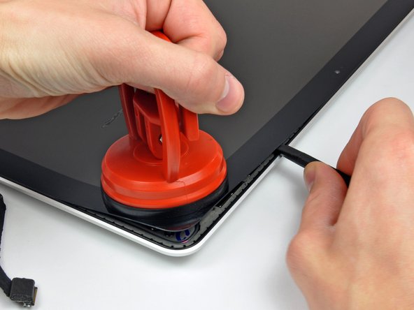
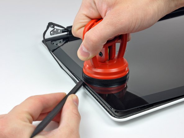
    • With the panel sufficiently heated, fasten a heavy-duty suction cup near the upper right corner of the display glass.

    • Don't fasten the suction cup on top of the rubber strip around the edge of the display glass.

    • To attach the suction cups we sell, first position the suction cup with the movable handle parallel to the face of the glass panel. While lightly holding the suction cup against the glass, raise the movable handle until it is parallel with the other handle.

    • Slowly and gently pull the corner of the display glass up off the display assembly.

    • If only the top edge of the glass lifts up (as seen in the third picture), repeat steps one and two until you can lift up the corner of the panel.

  21. Deze stap is niet vertaald. Help het te vertalen

    : stap 21, afbeelding 1 van 3 : stap 21, afbeelding 2 van 3 : stap 21, afbeelding 3 van 3
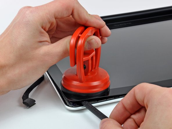
    • Gently lift the corner of the display glass enough to insert a spudger between it and the display assembly.

    • Use the flat end of a spudger to gently pry up the adhesive securing the front glass to the display.

    • Pry up the glass panel a few inches away from the upper right corner along the top and right edges of the display.

  22. Deze stap is niet vertaald. Help het te vertalen

    : stap 22, afbeelding 1 van 2 : stap 22, afbeelding 2 van 2
    • Use a heat gun to soften the adhesive under the black strip along the right side of the front glass panel.

    • Attach a suction cup along the right side of the front glass panel.

    • Pull up on the glass panel while you use the flat end of a spudger to separate it from the rest of the display assembly.

    • Continue working along the right edge of the front display glass until it is separated from the display.

    • It may be helpful to use a guitar pick or another thin plastic object to keep the upper right corner of the front glass panel from sticking back down to the display assembly.

  23. Deze stap is niet vertaald. Help het te vertalen

    : stap 23, afbeelding 1 van 2 : stap 23, afbeelding 2 van 2
    • Use your heat gun to soften the adhesive under the black strip along the top edge of the glass display panel.

    • Attach a suction cup near the top edge of the glass display panel and use it to pull the glass panel up off the display.

    • Work along the top edge of the glass panel, carefully using the flat end of a spudger to separate the adhesive if necessary.

  24. Deze stap is niet vertaald. Help het te vertalen

    : stap 24, afbeelding 1 van 2 : stap 24, afbeelding 2 van 2
    • Use a heat gun to soften the adhesive under the black strip near the upper left corner of the glass display panel.

    • Attach a suction cup near the upper left corner of the glass display panel.

    • Pull up on the suction cup and use the flat end of a spudger to carefully pry the glass display panel out of the display assembly.

    • Once the upper left corner has been separated from the display, it may be helpful to use a guitar pick or another thin plastic object to keep the glass from sticking back down to the display assembly.

  25. Deze stap is niet vertaald. Help het te vertalen

    : stap 25, afbeelding 1 van 2 : stap 25, afbeelding 2 van 2
    • Use a heat gun to soften the adhesive under the black strip along the left side of the front glass panel.

    • Attach a suction cup along the left side of the front glass panel.

    • Pull up on the glass panel while you use the flat end of a spudger to separate it from the rest of the display assembly.

    • Continue working along the left edge of the front display glass until it is separated from the display.

  26. Deze stap is niet vertaald. Help het te vertalen

    : stap 26, afbeelding 1 van 2 : stap 26, afbeelding 2 van 2
    • Now that the top, left, and right edges of the glass are free from the display, slowly lift the top edge of the glass panel and gently rotate it out of the display.

    • If necessary, use the flat end of a spudger to free the bottom edge of the glass display panel from the display assembly.

    • Before reassembling, be sure to clean both the inside of the glass display panel and the LCD as any dust or fingerprints trapped inside will be annoyingly visible when the machine is on.

  27. Deze stap is niet vertaald. Help het te vertalen

    : stap 27, afbeelding 1 van 2 : stap 27, afbeelding 2 van 2
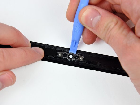
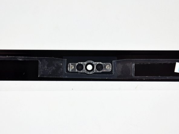
    • Insert the edge of a plastic opening tool between the display glass and the camera bracket, and run it around the camera bracket to separate it from the display glass.

    • Do not forget to stick the camera bracket down to the new front display glass before reassembly.

  28. Deze stap is niet vertaald. Help het te vertalen

    : stap 28, afbeelding 1 van 3 : stap 28, afbeelding 2 van 3 : stap 28, afbeelding 3 van 3
    • During the glass removal process, the camera cable may stick to the adhesive on the glass panel, disconnecting it from the camera board as the panel is lifted. If your camera cable is still connected to the camera board, skip this step.

    • To reconnect the cable, first use the tip of a spudger to remove the piece of foam tape over the camera cable ZIF socket.

    • Use the tip of a spudger to flip up the ZIF cable retainer on the camera cable socket.

    • Insert the camera cable into its socket on the camera board and use the tip of a spudger to snap down the ZIF cable retainer, locking the cable in place.

    • Reapply the piece of tape covering the camera cable socket.

  29. Deze stap is niet vertaald. Help het te vertalen

    : stap 29, afbeelding 1 van 2 : stap 29, afbeelding 2 van 2
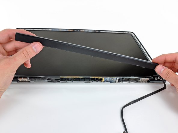
    • Slide the clutch cover toward the right edge of the display.

    • The clutch cover will move approximately .25" and stop. Do not force it too far to the right.

    • When reinstalling the clutch cover, be sure to slip it over the components protruding from the lower edge of the display about .25" to the right of its final installed position on the display.

  30. Deze stap is niet vertaald. Help het te vertalen

    : stap 30, afbeelding 1 van 2 : stap 30, afbeelding 2 van 2
    • Starting at its far left end, rock the clutch cover along its long axis while pulling it away from the clutch hinge.

    • Working from right to left, carefully continue to release and lift the clutch along the lower edge of the display assembly.

    • Lift the clutch cover up off the front bezel and set it aside.

    • When reinstalling the clutch cover, be sure to widen the opening when slipping it over the small black plastic cosmetic cover that fills the open end of the clutch cover when it is in place. The cosmetic cover has very thin and delicate plastic arms that hold it to the right clutch hinge.

  31. Deze stap is niet vertaald. Help het te vertalen

    : stap 31, afbeelding 1 van 1
    • Remove the six 2.9 mm Phillips screws securing the LCD panel to the front bezel.

  32. Deze stap is niet vertaald. Help het te vertalen

    : stap 32, afbeelding 1 van 1
    • Pull the LCD toward the top edge of the display to slide the circuitry along its lower edge out of the recess in the aluminum display assembly.

    • It may be helpful to use one hand to feed the display data cable through its channel in the aluminum display assembly as you pull the LCD toward the top edge of the display with the other hand.

  33. Deze stap is niet vertaald. Help het te vertalen

    : stap 33, afbeelding 1 van 1
    • Peel the piece of tape covering the display data cable connector away from the edge closest to the LCD.

  34. Deze stap is niet vertaald. Help het te vertalen

    : stap 34, afbeelding 1 van 2 : stap 34, afbeelding 2 van 2
    • Use the tip of a spudger to flip up the thin steel retaining clip securing the display data cable to its socket on the LCD.

    • Pull the display data cable straight away from its socket on the LCD.

    • Lift the LCD out of the display assembly and set it aside.

    • If you are replacing the LVDS/display data cable, simply de-route it from its slot cut into the display casing.

Eindstreep

35 andere personen hebben deze handleiding voltooid.

2 opmerkingen

I followed steps exept heatgun and I did it my expirience from1-10 is 2. Thanks

uho00 - Antwoord

4/4/2020 - I replaced the battery to my mid-2009 MacbookPro earlier, and so was comfortable with the early steps. Removing the battery and all the screws went well. Detaching cables was easy, but reattaching them was tough. Specifically, step 32 in reverse was the most difficult part. I recommend applying a new piece of electrical tape once you reattach the cable to keep them together. Otherwise trying to reassemble the lcd was impossible for me. I also had to extract the cable and re-thread it, attached to the lcd, clip side through the metal case. Once it was through there, I spent a few minutes delicately cleaning the lcd and the top screen. Ensuring everything was clean was also challenging. Re-assembly afterwards went well. Right away I turned on my computer and my screen was perfect. Coupled with the new battery and a round of Clean my Mac, and everything works perfectly. All the steps are correct, and this took a couple hours to complete.

Aaron Friedman - Antwoord

Voeg opmerking toe

Weergavestatistieken:

Afgelopen 24 uren: 4

Afgelopen 7 dagen: 6

Afgelopen 30 dagen: 24

Altijd: 39,668