Inleiding
Use this guide to remove and replace the PCB flashboard from your Canon EOS Rebel T6i camera. The PCB flashboard should be replaced following damage or exposure to the capacitor and/or the circuit itself. This is a step-by-step guide and each step should be followed in chronological order to ensure desired results.
You will need an iFixit opening tool, a spudger, a JIS #000 screwdriver, needle-nosed tweezers, a grounding strap, and a digital multimeter to complete the removal process.
Take caution when unassembling your Canon EOS Rebel T6i device. There is potential for device damage during the unassembling process.
CAUTION(Electric Shock): Be careful not to touch the terminals of the capacitor (black cylinder). This can cause the capacitor to discharge.
Wat je nodig hebt
-
-
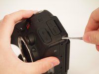
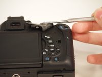
Remove two 6.8 mm JIS #000 screws on the right side.
-
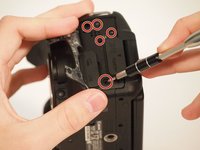
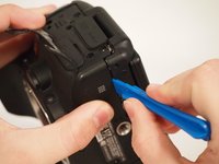
Remove six 5.3 mm JIS #000 screws on the bottom.
-
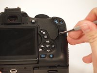
Remove two 5.3 mm JIS #000 screws on either side of the viewfinder.
-
-
Gereedschap gebruikt in deze stap:Tweezers$4.99
-
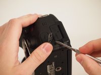
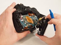
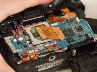
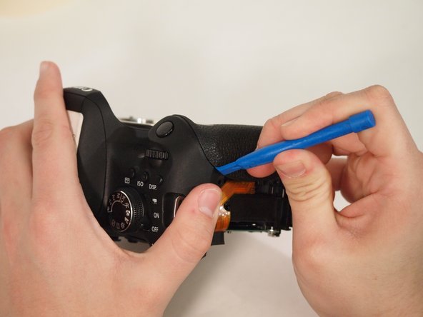
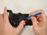
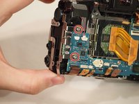
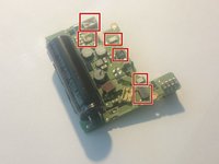
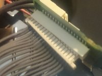
Remove the five ribbon connectors along the bottom of the assembly using either needle nose tweezers or a plastic opening tool to flip the small flaps to the "up" position.
-
Use a nylon spudger to pull each ribbon connector out of its connection using the hole in the center of the ribbon.
-
-
-
Remove the button cell battery from the motherboard using a pair of tweezers.
-
-
-
-
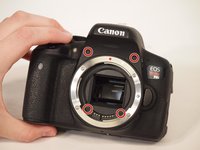
Remove the four screws from the front of the camera. There are two screws above the lens mount and two screws inside the lens mount.
-
Remove the four screws from the bottom of the camera.
On the Rebel T5i at least, the two screws inside the lens mount do not need to be removed. (They hold the lens flex connector in.)
I believe you are correct. I haven't specifically worked with a T6i either, but with all the other Canon Rebels I've dealt with, those two screws didn't need to be removed to take off the front cover.
Zephosk -
-
-
-
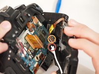
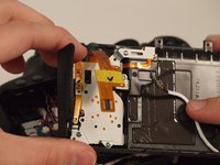
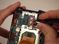
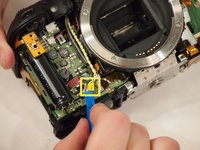
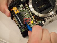
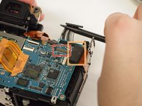
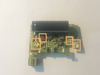
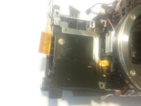
Remove the yellow and red connections on the front near the black cylinder (capacitor).
-
The yellow connector will just pop out if pried from the bottom using a plastic opening tool.
-
The red connector will pull out of the casing with either a plastic opening tool or a thin set of tweezers.
-
-
-
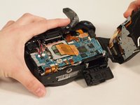
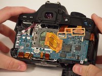
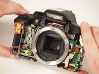
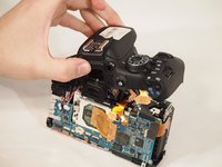
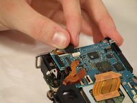
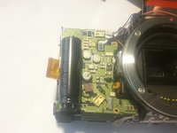
Remove the entire upper flash assembly by gently pulling it up and off the camera.
What is the black wire-looking thing that hangs down from the flash/top cover assy? Doesnt have a connector on it, seems to be made of rubber. It goes up to the built-in flash head and seems to be epoxied to it. WiFi antenna? Doesnt really make sense bevause its not attached to the mainboard as far as I can tell. In the second picture above, it is the black thing hanging down in front od the underside of the dial.
Where does that go when you put it back together?
-
-
-
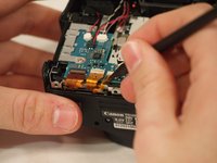
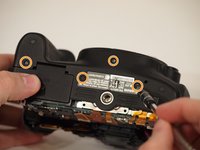
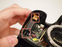
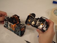
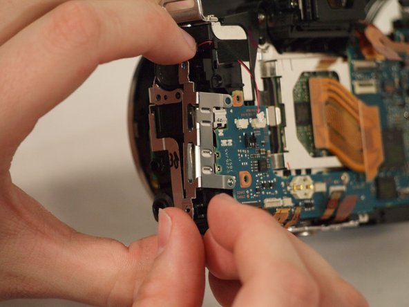
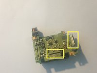
Disconnect the ribbon connector on the upper right side of the motherboard.
-
Pull back the foam on the connector on the far right side of the motherboard.
-
Flip up the tab on the connector and remove the cable.
-
-
-
Place a voltmeter in parallel with the capacitor. If a charge is detected, make sure the battery is removed from the device.
-


To reassemble your device, follow these instructions in reverse order.
To reassemble your device, follow these instructions in reverse order.
Annuleren: ik heb deze handleiding niet afgemaakt.
Één andere persoon heeft deze handleiding voltooid.
Team

University of Memphis, Team S2-G1, Kim Spring 2018 Lid van University of Memphis, Team S2-G1, Kim Spring 2018
UM-KIM-S18S2G1
3 Leden
11 handleidingen geschreven