Ga door naar hoofdinhoud

CM Storm QuickFire Rapid Switch Replacement

Wat je nodig hebt

  1. CM Storm QuickFire Rapid Switch Replacement, Switch: stap 1, afbeelding 1 van 2 CM Storm QuickFire Rapid Switch Replacement, Switch: stap 1, afbeelding 2 van 2
  2. CM Storm QuickFire Rapid Switch Replacement, Remove screw on back of keyboard (labeled do not remove): stap 2, afbeelding 1 van 2 CM Storm QuickFire Rapid Switch Replacement, Remove screw on back of keyboard (labeled do not remove): stap 2, afbeelding 2 van 2
    • Using a Philips #0 screwdriver, remove the .5cm screw from the back of the keyboard.

    • This will void your warranty!

    • When inserting the screw after replacing the switch, make sure to not screw in too tight. This may cause erratic behavior with the keyboard.

  3. CM Storm QuickFire Rapid Switch Replacement, Seperating Back Panel from Front Panel: stap 3, afbeelding 1 van 3 CM Storm QuickFire Rapid Switch Replacement, Seperating Back Panel from Front Panel: stap 3, afbeelding 2 van 3 CM Storm QuickFire Rapid Switch Replacement, Seperating Back Panel from Front Panel: stap 3, afbeelding 3 van 3
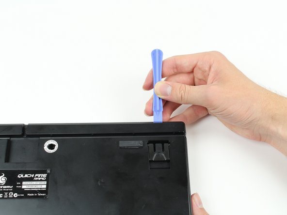
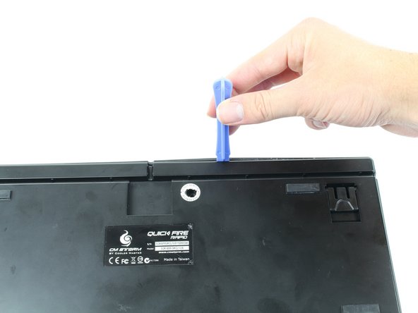
    • Wedge a plastic opening tool between the rear plate and rim of the keyboard and slide it through the circled areas to separate the plastic hooks that mount the rim to the rear plate.

  4. CM Storm QuickFire Rapid Switch Replacement, Opening Back Panel: stap 4, afbeelding 1 van 2 CM Storm QuickFire Rapid Switch Replacement, Opening Back Panel: stap 4, afbeelding 2 van 2
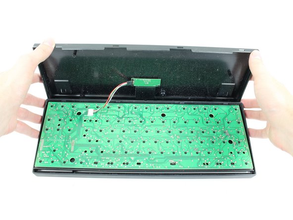
    • Firmly grasp the bottom panel of the keyboard and carefully detach it from the rest of the board.

    • Do not put strain on the ribbon cable when lifting the bottom panel.

  5. CM Storm QuickFire Rapid Switch Replacement, Detaching SIL Connector: stap 5, afbeelding 1 van 2 CM Storm QuickFire Rapid Switch Replacement, Detaching SIL Connector: stap 5, afbeelding 2 van 2
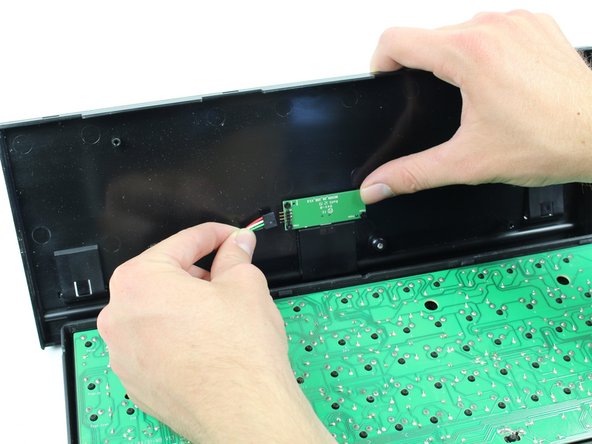
    • Detach the 4-pin cable from the bottom panel of the keyboard.

  6. CM Storm QuickFire Rapid Switch Replacement, Desolder Switch Solder Joints: stap 6, afbeelding 1 van 1
    • Desolder the joints holding the switch to the board.

    • Remove the switch and solder the new switch in place.

Conclusie

To reassemble your device, follow these instructions in reverse order.

9 andere personen hebben deze handleiding voltooid.

Andrew

Lid sinds: 10/12/14

321 Reputatie

2 handleidingen geschreven

Team

Cal Poly, Team 6-23, Maness Fall 2014 Lid van Cal Poly, Team 6-23, Maness Fall 2014

CPSU-MANESS-F14S6G23

4 Leden

12 handleidingen geschreven

0 opmerkingen

Voeg opmerking toe

Weergavestatistieken:

Afgelopen 24 uren: 1

Afgelopen 7 dagen: 14

Afgelopen 30 dagen: 77

Altijd: 15,758