Inleiding
This guide shows how to remove the body panels of the Pentax MZ-S. This is useful to troubleshoot basic control malfunctions and is also the starting point of more in depth repairs.
Wat je nodig hebt
-
-
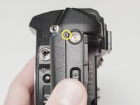
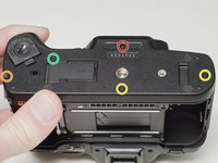
Remove two 7.5 mm #00 screws.
-
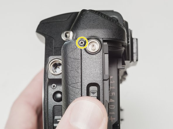
Remove one 9.0 mm #00 screw.
-
Remove one 13.5 mm #00 screw from inside the battery compartment.
-
-
-
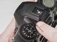
Push the button to pop up the flash.
-
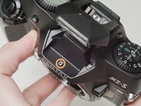
Remove one 3.5 mm #00 screw.
-
Remove one 5.5 mm #00 screw.
-
-
-
Carefully lift the top cover away from the body to access wired connections.
-
-
-
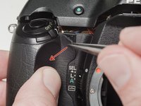
Peel back the corner of the rubber grip.
-
Remove the small plastic cover.
-
-
-
-
Use a 1kΩ-10kΩ high power resistor to discharge the capacitor. Place the resistor between the blue wire, exposed in the previous step, and ground.
-
-
-
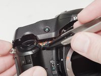
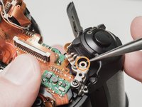
Carefully lift the sides of the white latch.
-
-
-
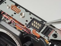
Desolder the red wire.
-
Carefully lift the sides of the white latch.
-
-
-
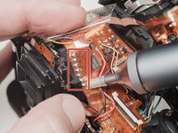
Desolder blue, black, brown and green wires.
-
Remove the loose shim washer if present.
-
-
-
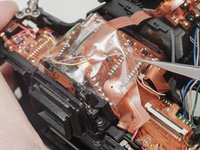
Remove the piece of cellophane tape covering the flex connections.
-
Desolder flex connetions.
-
-
-
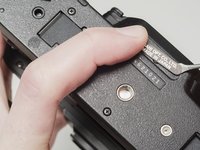
Use isopropyl alcohol to soften the adhesive under the country plate and remove.
-
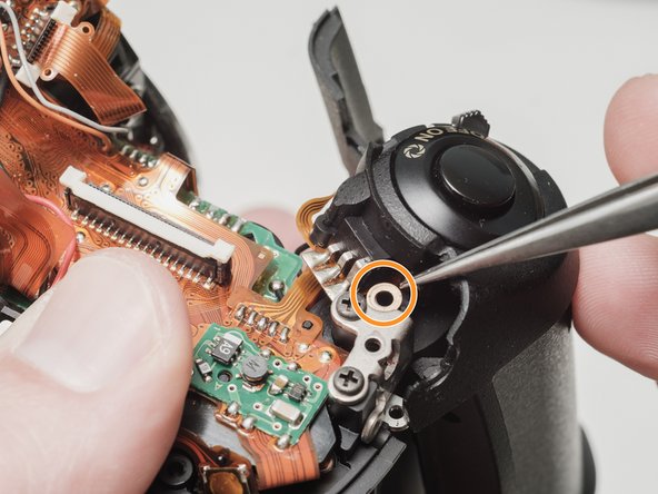
Remove one 5mm #00 screw.
-
Remove one 7.5mm #00 screw.
-
Remove two 4.5mm #00 screws.
-
Remove one 5.5mm #00 screw.
-
Remove the plastic frame around the accessory grip contacts.
-
-
-
Remove one 4.0 mm #00 screw.
-
Remove left cover.
-
-
-
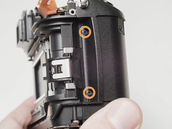
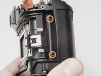
Remove one 6.0 mm #00 screw.
-
Remove two 3.5 mm #00 screws.
-
Remove one 5.0 mm #00 screw.
-
Remove the strap lug.
-
-
-
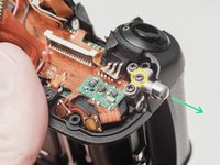
Carefully pull the right panel away from the body. It is still attached.
-
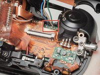
Desolder the flex connections.
-


To reassemble your device, follow these instructions in reverse order.