How do I remove the RAM?
Does this laptop have a removable RAM and how do I do that?
Is dit een goede vraag?
Score
0

Does this laptop have a removable RAM and how do I do that?
Is dit een goede vraag?

Rep: 1
![]() 3
3
![]() 1
1
![]() 1
1
Before removing a memory module, follow these steps:
1. Shut down the computer. If you are unsure whether the computer is off or in Hibernation, turn the
computer on, and then shut it down through the operating system.
2. Disconnect all external devices connected to the computer.
3. Disconnect the power from the computer by first unplugging the power cord from the AC outlet and
then unplugging the AC adapter from the computer.
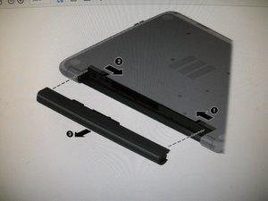
To remove the battery:
1. Position the computer upside down on a flat surface.
2. Slide the battery lock latch (1), and then slide the battery release latch (2) to release the battery.
3. Remove the battery from the computer (3).
4. Remove the battery and then remove the following components:
● Keyboard :
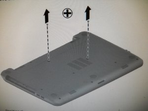
1. Position the computer upside down with the front toward you.
2. Remove the two Phillips PM2.5×5.0 screws that secure the keyboard to the computer.
3. Position the computer upright with the front toward you.
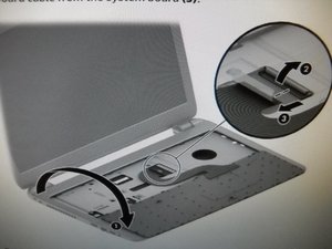
4. Lift to rotate up the top of the keyboard (1), and then lift the keyboard (2) to disengage it from the
computer.
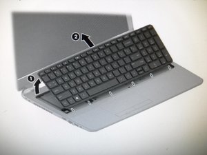
5. Rotate the keyboard over onto the palm rest (1), and the lift the ZIF connector (2) and disconnect the
keyboard cable from the system board (3).
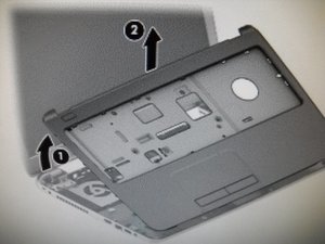
● Top cover:
To remove the top cover:
1. Position the computer upside down with the front toward you.
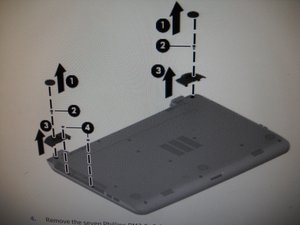
2. Remove the rear covers by prying off the two rubber feet (1), removing the two Phillips PM2.5×8.0
screws (2) that secure the rear covers to the computer, and then lifting the rear covers off the computer
3. Remove the two Phillips broadhead PM2.5×2.0 screws from the optical drive bay (4).
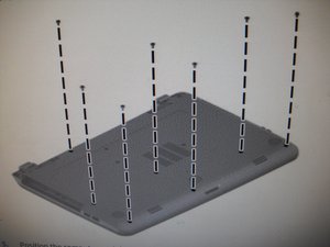
4. Remove the seven Phillips PM2.5×5.0 screws that secure the top cover to the computer.
5. Position the computer upright with the front toward you.
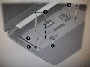
6. Disconnect the power button board cable (1) and the touchpad button board cable (2).
7. Remove the four Phillips PM2.5×5.0 screws (3) that secure the top cover to the computer.
8. Lift the rear edge of the top cover (1) until it disengage from the base enclosure.
9. Remove the top cover (2).
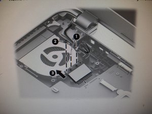
● WLAN module:
To remove the WLAN module:
1. Disconnect the WLAN antenna cables (1) from the terminals on the WLAN module.
NOTE: The #1 WLAN antenna cable is connected to the WLAN module Main terminal. The #2 WLAN
antenna cable is connected to the WLAN module Aux terminal.
2. Remove the Phillips PM2.0×3.0 screw (2) that secures the WLAN module to the system board. (The
WLAN module tilts up.)
3. Remove the WLAN module by pulling the module away from the slot at an angle (3).
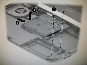
● Hard drive:
To remove the hard drive:
1. Remove the two Phillips PM2.5×5.0 screws (1) that secure the hard drive to the computer.
2. Slide the hard drive to disengage it from the connector (2).
3. Lift the hard drive from the computer (3).
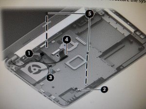
● System board:
To remove the system board:
1. Position the computer upright, and then disconnect the following cables from the system board:
(1): Power connector cable
(2): Speaker cable
(3): Fan cable
(4): Display cable
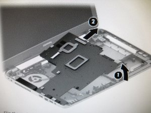
2. Remove the two Phillips PM2.5×5.0 screws (5) that secure the system board to the computer.
To remove a memory module:
3. Lift the right side of the system board (1), and then pull the board away from the computer enough to
disengage the connectors from the side of the base enclosure (2).
NOTE: Be careful not to inadvertently disconnect the speaker cable when lifting the system board.
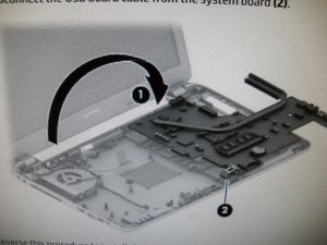
4. Flip the system board upside down to gain access to the speaker connector (1).
5. Disconnect the USB board cable from the system board (2).
To remove a memory module:
1. Spread the retaining tabs (1) on each side of the memory module slot to release the memory module.
(The memory module tilts up.)
2. Remove the memory module (2) by pulling it away from the slot at an angle.
Was dit antwoord nuttig?
Afgelopen 24 uren: 0
Afgelopen 7 dagen: 8
Afgelopen 30 dagen: 29
Altijd: 522