Inleiding
This is a draft teardown of a 3rd party Combat Arcade Stick, Model No. G5758, designed by Intec for the Nintendo Wii console.
This arcade stick was available at a very cheap price compared to many similar models for sale around the time, mainly because of its exclusive compatibility with the Nintendo Wii using a connection similar to a Classic Controller attached to a Wii Remote; it was also sourced and manufactured using very cheap plastic parts and frail wiring connections.
While the unit can be opened for basic maintenance and cleaning, it's very difficult to repair or replace some sub-components without making the device inoperable, because there are several permanently-soldered connections between each piece.
Still, this stick may be a worthwhile DIY build if one is willing to desolder, dismantle and rebuild many of its weaker parts.
Wat je nodig hebt
-
-
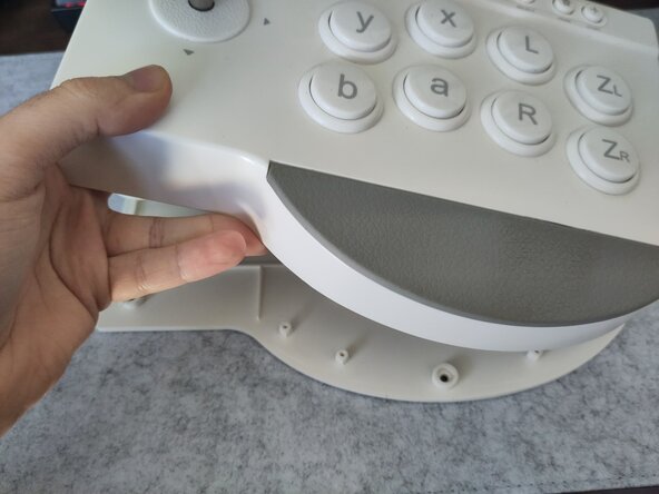
Remove the six Phillips-head screws under the rubber feet around the bottom of the case.
-
Flip the case right-side up, and lift up the top to remove the bottom plate.
-
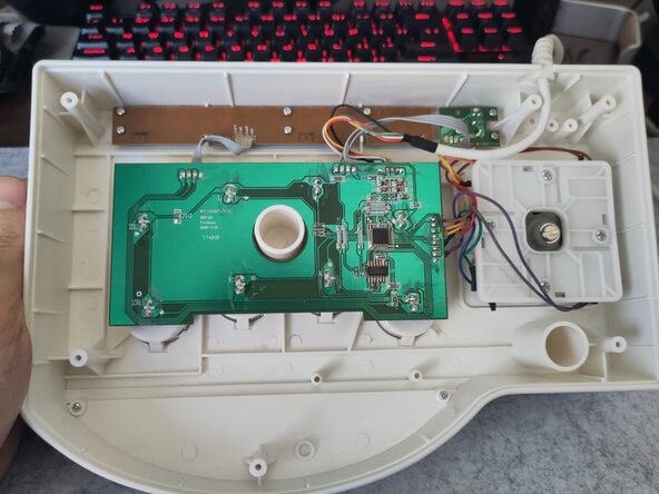
There are four main components underneath:
-
The main PCB, which holds the main buttons, surface-mounted chips, and connections to the other three components.
-
the joystick, connected to the main PCB by eight wires soldered to each part of the stick's microswitches.
-
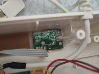
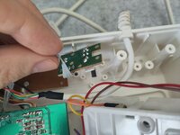
the turbo daughterboard, a small PCB with a switch and an LED, wired to the main PCB, intended to enable turbo functionality on the main buttons.
-
the menu button daughterboard, a long PCB with three small push buttons, with a simple ground connection back to the main PCB.
-
-
-
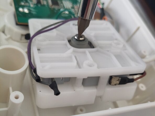
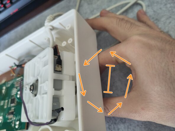
The restrictor gate is held in place by 4 Phillips-head screws.
-
The grey balltop can be removed by inserting a flat screw driver in the line-shaped divot in the middle, then use your hand on the other side to unscrew.
-
-
-
-
The little circuit board holding the turbo switch and LED is held in place by 3 Phillips-head screws.
-
-
-
The separate circuit board holding the three menu buttons is held in place by a couple Philips-head screws on each side.
-
-
-
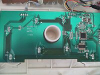
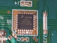
Shown in first picture is the main circuit board.
-
All other components, including buttons, stick, and daughterboards are soldered at various connection points around the board. There are no socketed components, and even the buttons must be desoldered to remove them.
-
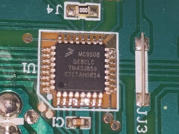
One chip on the board reads:
-
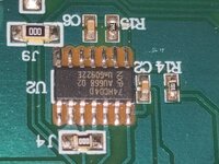
Another chip reads: 74HC04F NXP
-