Ga door naar hoofdinhoud

Vue éclatée du Motorola Droid Bionic

Stap 13
Motorola Droid Bionic Teardown: stap 0, afbeelding 1 van 2 Motorola Droid Bionic Teardown: stap 0, afbeelding 2 van 2
  • There's tons of chips on the front of the board. Other chips of interest include:

  • Texas Instruments WL1271 chip that supports WiFi (802.11 b/g/n), Bluetooth 2.1, FM and GPS technologies (thanks Chipworks!)

  • Kionix KXTF9 accelerometer

  • ST Micro AGD8 2040 S6NBF gyroscope

  • Avago ACPM-7868 quad-band power amplifier

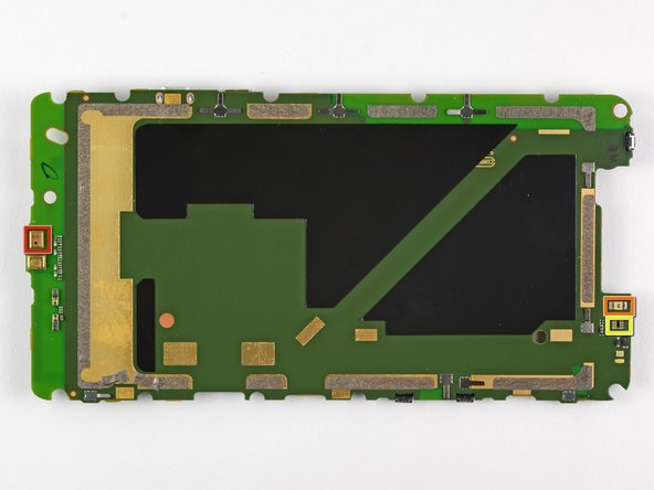
  • What's this? Did we use Content Aware to remove all of the chips from the back of the motherboard? The answer is no; there just isn't much going on with the backside of the board.

  • We find a microphone (red), proximity sensor (orange), ambient light sensor (yellow) on the back.

  • It is possible that Motorola placed all of the chips on one side of the board to keep the thickness of the device to a minimum.

Il y a des tonnes de puces sur la carte. Parmi les autres puces intéressantes :

Puce Texas Instruments WL1271 qui gère les technologies WiFi (802.11 b/g/n), Bluetooth 2.1, FM et GPS (merci Chipworks !)

Accéléromètre Kionix KXTF9

Gyroscope ST Micro AGD8 2040 S6NBF

Amplificateur de puissance quadri-bande Avago ACPM-7868

Qu'est-ce que c'est que ça ? Qui a détaché les puces au dos de la carte mère ? Personne, en fait c'est juste qu'il n'y a pas beaucoup d'ambiance au dos de la carte.

Nous y trouvons un microphone (rouge), un capteur de proximité (orange), un capteur de luminosité ambiante (jaune).

Il est possible que Motorola ait placé toutes les puces d'un côté de la carte pour minimiser l'épaisseur de l'appareil.

Je bijdragen zijn gelicentieerd onder de open source Creative Commons-licentie.