Deze versie kan foutieve bewerkingen bevatten. Schakel over naar de recentste gecontroleerde momentopname.
Wat je nodig hebt
-
-
Schakel je iPhone uit voordat je begint deze uit elkaar te halen.
-
Verwijder de twee 3.4 mm lange P2 Pentalobe schroeven aan de onderkant van de iPhone, naast de Lightning-connector.
-
-
-
Trek de blauwe hendel naar achteren zodat de anti-klem vrij kan bewegen. (Op deze manier deactiveer je de openingsstand van de anti-klem.)
-
Schuif de armen over de linker- of rechterzijde van je iPhone.
-
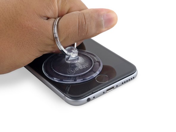
Plaats de zuignappen dichtbij de onderkant van de telefoon—één op de voorkant en één aan de achterkant.
-
Druk beide zuignappen aan, om zuigkracht uit te oefenen op de gewenste plek.
-
-
-
Trek het blauwe handvat naar voren om de armen van de anti-klem te vergrendelen.
-
Draai het handvat 360 graden met de klok mee of tot de zuignappen uit beginnen te rekken.
-
Zodra de anti-klem een opening heeft weten te creëren die groot genoeg is, steek je een openingsplectrum in de opening.
-
Sla de volgende drie stappen over.
-
-
-
Het is een optie om de onderkant van de iPhone gedurende een minuut te verwarmen met het gebruik van een iOpener of een föhn.
-
-
-
Pak de schermmodule voorzichtig vast en til deze op om de telefoon te openen. Gebruik de klemmen aan de bovenkant van het scherm als een scharnier om de telefoon te openen.
-
Open het scherm totdat deze ongeveer een hoek van 90º beschrijft en laat het scherm vervolgens leunen op een voorwerp, zodat je aan de telefoon kunt werken.
-
Je kunt bijvoorbeeld een elastiek gebruiken om de schermmodule te verbinden aan een voorwerp, waardoor deze rechtop blijft staan. Dit voorkomt ook dat je de kabels onbedoeld en te veel belast.
-
-
-
Verwijder de twee Phillips schroeven die het plaatje op de batterijaansluiting bevestigen, met de volgende lengtes:
-
Eén 2.9 mm lange schroef
-
Eén 2.2 mm lange schroef
-
-
-
-
Verwijder de volgende vier Phillips schroeven die het plaatje boven op de schermkabel bevestigen:
-
Drie 1.2 mm lange schroeven
-
Eén 2.8 mm lange schroef
-
-
Deze stap is niet vertaald. Help het te vertalen
-
Use the flat end of a spudger to disconnect the rear camera from its socket on the logic board.
-
-
Deze stap is niet vertaald. Help het te vertalen
-
Remove the following two Phillips screws over the rear camera bracket:
-
One 1.6 mm screw
-
One 2.0 mm screw
-
-
Deze stap is niet vertaald. Help het te vertalen
-
Insert a spudger to the side of the camera, between the rear case and the camera module.
-
Gently pry up on the camera to nudge it out from its housing.
-
-
Deze stap is niet vertaald. Help het te vertalen
-
Insert a SIM card eject tool or a paperclip into the small hole in the SIM card tray.
-
Press to eject the tray.
-
-
Deze stap is niet vertaald. Help het te vertalen
-
Remove the two 2.3 mm Phillips screws securing the upper component cable connector bracket.
-
-
Deze stap is niet vertaald. Help het te vertalen
-
Remove the upper component cable connector bracket.
-
-
Deze stap is niet vertaald. Help het te vertalen
-
Remove the following five Phillips screws securing the top left Wi-Fi antenna:
-
Two 1.5mm screws
-
One 2.3 mm screw
-
One 1.9 mm screw
-
One 2.0 mm screw
-
-
Deze stap is niet vertaald. Help het te vertalen
-
Use the flat end of a spudger to disconnect the audio control cable from its socket on the logic board.
-
-
Deze stap is niet vertaald. Help het te vertalen
-
Use the pointed tip of a spudger to disconnect the antenna cable from its socket on the upper right corner of the logic board.
-
-
Deze stap is niet vertaald. Help het te vertalen
-
Use the pointed tip of a spudger to disconnect the antenna cable from its socket on the lower left corner of the logic board.
-
-
Deze stap is niet vertaald. Help het te vertalen
-
Insert the flat end of a spudger underneath the Lightning connector ribbon cable. Lift up to disconnect it from its socket on the logic board.
-
-
Deze stap is niet vertaald. Help het te vertalen
-
Gently pull up on the antenna cable to de-route it from the two clips on the right side of the logic board.
-
-
Deze stap is niet vertaald. Help het te vertalen
-
Remove the 1.3 mm Phillips screw securing the NFC bracket to the logic board.
-
-
Deze stap is niet vertaald. Help het te vertalen
-
Remove the following two Phillips screws:
-
One 2.5 mm screw at the top of the logic board
-
One 1.4 mm screw set into the upper edge of the rear case
-
-
Deze stap is niet vertaald. Help het te vertalen
-
Remove the final three screws securing the logic board to the rear case:
-
One 1.9 mm Phillips screw
-
One 2.5 mm hex nut
-
One 1.8 mm Phillips screw
-
-
Deze stap is niet vertaald. Help het te vertalen
-
Insert an opening pick below the lower edge of the logic board, between the board and the loudspeaker.
-
Use the opening pick to gently lift the logic board out of its housing.
-
Remove the logic board.
-


Annuleren: ik heb deze handleiding niet afgemaakt.
224 andere personen hebben deze handleiding voltooid.

33 opmerkingen
So all the logic boards come with the components installs? Like the High band PAD, power amplifier avago, power amplifier Skyworks, power amplifier TriQuint, LTE modem Qualcomm, and lastly the Apps processor Apple SoC stacked on Elpida RAM. Here I thought you had to buy them.
I'm also assuming that some don't. I would like to know that alternative.
Yup! The SSD is a flash memory chip hidden underneath an EMI shield on the logic board. You can see it in our teardown.
Um, no, actually the NAND/ssd/flash/storage chip is the big Toshiba one in the middle, it’s the one next to the line of capacitors, and is not under the shields. there are shields on either side of it. Look at the teardown page you linked to yourself and you will confirm what I’ve said.
great guide worked perfectly, had some minor water damaged internals with a completely good logic board, replaced it in a 16g pos basically have a brand new 128g 6s