Ga door naar hoofdinhoud

Deze versie kan foutieve bewerkingen bevatten. Schakel over naar de recentste gecontroleerde momentopname.

Wat je nodig hebt

  1. Deze stap is niet vertaald. Help het te vertalen

    : stap 1, afbeelding 1 van 1
    • Lay your iMac front side down on a table with the lower edge facing yourself.

    • Loosen the single Phillips screw in the center of the access door.

    • This screw is captive in the access door.

    • Remove the access door from your iMac.

  2. Deze stap is niet vertaald. Help het te vertalen

    : stap 2, afbeelding 1 van 2 : stap 2, afbeelding 2 van 2
    Gereedschap gebruikt in deze stap:
    Heavy-Duty Suction Cups (Pair)
    $14.95
    Koop
    • The glass panel is fixed onto the front bezel with fourteen magnets around its perimeter.

    • Stick two suction cups to opposing corners of the glass panel.

    • To attach the suction cups we sell, first position the suction cup with the movable handle parallel to the face of the glass panel. While lightly holding the suction cup against the glass, raise the movable handle until it is parallel with the other handle.

    • If your suction cups refuse to stick, try cleaning both the glass panel and the suction cup with a mild solvent.

  3. Deze stap is niet vertaald. Help het te vertalen

    : stap 3, afbeelding 1 van 1
    • Gently pull the glass panel straight up off the iMac.

    • The glass panel has several positioning pins around its perimeter. To avoid shearing these pins off the glass panel, be sure to only pull straight up during removal.

    • Be meticulous about cleaning the LCD and the inside face of the glass panel before reinstallation, as any fingerprints or dust trapped inside will be annoyingly visible when the display is on.

    • When replacing the glass, be sure there's nothing between the glass and the frame. Stray cables could be damaged or crack the glass.

  4. Deze stap is niet vertaald. Help het te vertalen

    : stap 4, afbeelding 1 van 1
    • Remove the following 12 screws securing the front bezel to the rear case:

    • Eight 13 mm T8 Torx.

    • Four 25 mm T8 Torx.

    • On the 24" iMac Intel Model A1225, the bottom center two screws are long (26mm), four on sides (two left, two right) are medium (18mm), and the remaining 6 (four top, two bottom corners) are short (14mm).

  5. Deze stap is niet vertaald. Help het te vertalen

    : stap 5, afbeelding 1 van 2 : stap 5, afbeelding 2 van 2
    • The front bezel is still attached to the iMac by the microphone cable.

    • Gently lift the front bezel from its top edge off the rear case.

    • Once the top edge of the front bezel has cleared the rear case, rotate the front bezel toward the stand and lift it off the rear case.

    • Rotate the front bezel away from the rest of the device and lay it above the top edge of the iMac.

    • When reinstalling the front bezel, start at the lower edge and make sure it is flush with the rear case before lowering the top edge onto the iMac.

  6. Deze stap is niet vertaald. Help het te vertalen

    : stap 6, afbeelding 1 van 1
    • Disconnect the microphone cable connector, removing tape as necessary.

    • For the front bezel to sit properly, be sure to tuck the microphone cable and connector into the void next to the camera board.

  7. Deze stap is niet vertaald. Help het te vertalen

    : stap 7, afbeelding 1 van 3 : stap 7, afbeelding 2 van 3 : stap 7, afbeelding 3 van 3
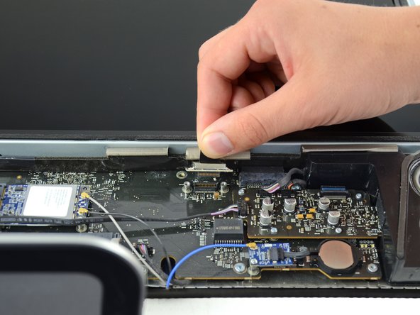
    • Remove the two 5.3 mm T6 torx screws from the LCD connector.

    • Firmly grasp the pull tab on top of the connector and pull it straight up out of its port.

    • Make sure that you are pulling the tab and not the connector cable.

  8. Deze stap is niet vertaald. Help het te vertalen

    : stap 8, afbeelding 1 van 1
    • Remove the eight T8 Torx screws securing the display panel to the rear case.

    • The iMac shown is a 20" model, but the screw locations should be approximately correct.

  9. Deze stap is niet vertaald. Help het te vertalen

    : stap 9, afbeelding 1 van 3 : stap 9, afbeelding 2 van 3 : stap 9, afbeelding 3 van 3
    • Place your hands on either side of the bottom of the display panel, and lift it up enough that you can reach the connectors inside.

    • Do not try to remove the display panel completely as it is still connected to the rest of the device.

    • While holding the display panel up with one hand, locate and remove the display thermal sensor cable from its connector.

  10. Deze stap is niet vertaald. Help het te vertalen

    : stap 10, afbeelding 1 van 2 : stap 10, afbeelding 2 van 2
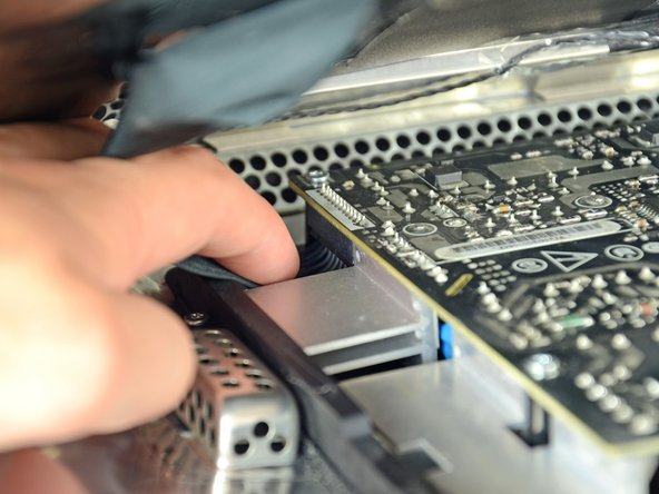
    • While still holding the display panel up, use two fingers to firmly push down on the power supply cable connector from its socket.

    • Be very careful not to touch the exposed face of the power supply to avoid electric shock from the many large capacitors attached to the other side of the board.

  11. Deze stap is niet vertaald. Help het te vertalen

    : stap 11, afbeelding 1 van 1
    • Lift and remove the display panel from the device.

  12. Deze stap is niet vertaald. Help het te vertalen

    : stap 12, afbeelding 1 van 1
    • Commencez par suivre l'excellent guide de Jeff Dickson du step 2 jusqu'au step 9 (demontage de la logic board)

  13. Deze stap is niet vertaald. Help het te vertalen

    : stap 13, afbeelding 1 van 1
    • Retirer les stickers de preuve de garantie.

    • Débrancher le capteur de temperature CPU.

  14. Deze stap is niet vertaald. Help het te vertalen

    : stap 14, afbeelding 1 van 2 : stap 14, afbeelding 2 van 2
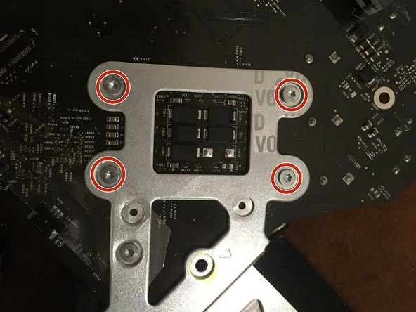
    • Dévisser les 4 vis radiateur a l'aide du tournevis Philips #2

    • Retourner la logic board

    • Finir de dévisser et retirer les 4 vis torx 8

  15. Deze stap is niet vertaald. Help het te vertalen

    : stap 15, afbeelding 1 van 2 : stap 15, afbeelding 2 van 2
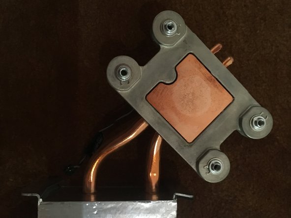
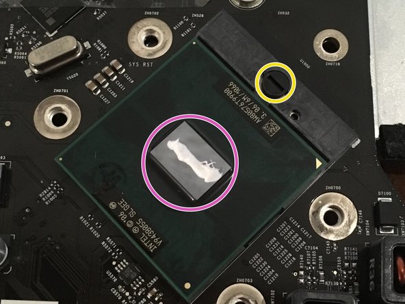
    • Nettoyer le surplus de pate thermique à l'aide d'un chiffon propre et d'une solution alcoolique.

    • Se tenir loin de la logic board et autres pieces électronique durant l'étape de nettoyage.

  16. Deze stap is niet vertaald. Help het te vertalen

    : stap 16, afbeelding 1 van 1
    • Dévisser d'un demi tour la vis de blocage du CPU à l'aide d'un petit tournevis plat.

    • Le support doit légèrement reculer lors du déblocage.

    • Retirer délicatement le processeur en le tirant verticalement.

  17. Deze stap is niet vertaald. Help het te vertalen

    : stap 17, afbeelding 1 van 2 : stap 17, afbeelding 2 van 2
    • Aligner le nouveau processeur grâce au détrompeur.

    • Deposer le nouveau processeur verticalement dans son logement.

    • Ne surtout pas forcer, le CPU doit rentrer tout seul.

    • Revisser la vis de blocage d'un demi tour.

    • Deposer un peu de pâte thermique sur le centre du CPU.

    • Lors de l'étape de remontage du radiateur, étaler la pâte en pressant doucement le radiateur sur le CPU avant de le visser.

Eindstreep

7 andere personen hebben deze handleiding voltooid.

Bastien Arata

Lid sinds: 06/29/16

474 Reputatie

1 Handleiding geschreven

Één opmerking

Anyone have any tips or advice as to what CPUs would work best?

May Goodman - Antwoord

Voeg opmerking toe

Weergavestatistieken:

Afgelopen 24 uren: 6

Afgelopen 7 dagen: 25

Afgelopen 30 dagen: 137

Altijd: 10,220