Deze versie kan foutieve bewerkingen bevatten. Schakel over naar de recentste gecontroleerde momentopname.
Wat je nodig hebt
-
-
Koppel je iMac's stroomkabel en alle andere aangesloten apparaten los.
-
Leg je iMac met het scherm naar beneden neer, op een zachte en schone ondergrond.
-
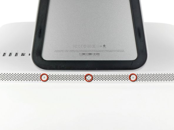
Maak de drie kruiskopschroeven (Phillips) los, die de toegangsdeur aan de onderkant van de iMac bevestigen.
-
Verwijder de toegangsdeur.
-
-
Deze stap is niet vertaald. Help het te vertalen
-
Gently slide the black plastic RAM pull tab out from the RAM slot.
-
Pull the black plastic tab away from the bottom edge of the iMac to eject the module(s) on that side of the RAM bay.
-
-
Deze stap is niet vertaald. Help het te vertalen
-
Slide the old RAM module(s) out of their slots in the RAM bay and set them aside.
-
-
Deze stap is niet vertaald. Help het te vertalen
-
Repeat the process in the previous steps to remove the RAM module(s) from the other side of the RAM bay.
-
-
Deze stap is niet vertaald. Help het te vertalen
-
Be sure the small notch cut into each RAM module (shown in the first picture) mates with the protrusion in each RAM slot (shown in the second picture).
-
-
Deze stap is niet vertaald. Help het te vertalen
-
Stick a suction cup near each of the two top corners of the glass panel.
-
If your suction cups refuse to stick, try cleaning both the glass panel and the suction cup with a mild solvent.
-
-
Deze stap is niet vertaald. Help het te vertalen
-
Gently lift the glass panel perpendicular to the face of the LCD enough to clear the steel mounting pins attached along the underside of the top edge of the glass panel.
-
Pull the glass panel away from the lower edge of the iMac and carefully set it aside.
-
-
Deze stap is niet vertaald. Help het te vertalen
-
Remove the eight 8 mm T10 Torx screws securing the display to the outer case.
-
-
Deze stap is niet vertaald. Help het te vertalen
-
Slightly lift the top edge of the display out of the outer case.
-
-
Deze stap is niet vertaald. Help het te vertalen
-
Pull the vertical sync cable connector out of its socket on the LED driver board near the top left corner of your iMac.
-
-
Deze stap is niet vertaald. Help het te vertalen
-
Rotate the display out of the outer case enough to disconnect the LED backlight power cable from the LED driver board.
-
-
Deze stap is niet vertaald. Help het te vertalen
-
Pull the display data cable straight out of its socket on the logic board.
-
-
Deze stap is niet vertaald. Help het te vertalen
-
Disconnect the LCD thermal sensor cable connector from its socket on the logic board.
-
-
Deze stap is niet vertaald. Help het te vertalen
-
Carefully pull the display toward the top edge of your iMac and lift it out of the outer case, minding any cables that may get caught.
-
-
Deze stap is niet vertaald. Help het te vertalen
-
Remove the following four screws:
-
One 9.3 mm T10 Torx screw with a large head
-
Three 9.3 mm T10 Torx screws with a normal sized head
-
-
Deze stap is niet vertaald. Help het te vertalen
-
Pull the optical drive thermal sensor connector toward the top edge of the iMac to disconnect it from its socket on the logic board.
-
-
Deze stap is niet vertaald. Help het te vertalen
-
Lift the inner edge of the optical drive and maneuver its connector past the GPU frame attached to the logic board.
-
Carefully pull the optical drive off its mounting pins on the right side of the outer case to gain clearance for disconnecting the optical drive cable.
-
Allow the optical drive to hang down as you de-route the optical drive thermal sensor connector from behind the GPU heat sink.
-
-
-
Deze stap is niet vertaald. Help het te vertalen
-
Disconnect the optical drive cable by pulling its connector away from the optical drive.
-
Remove the optical drive from the iMac.
-
-
Deze stap is niet vertaald. Help het te vertalen
-
Remove the single 13 mm T10 Torx screw securing the optical drive fan to the outer case.
-
-
Deze stap is niet vertaald. Help het te vertalen
-
Pull the optical drive fan off the pins attached to the outer case.
-
-
Deze stap is niet vertaald. Help het te vertalen
-
Pull the optical drive fan connector out of its socket on the logic board.
-
Remove the optical drive fan from the iMac.
-
-
Deze stap is niet vertaald. Help het te vertalen
-
In the proceeding steps, you will disconnect the following cables:
-
SD Board and microphone
-
Left/Right Speaker
-
Wi-Fi Antenna
-
Bluetooth/Ambient Light Sensor/Camera/Left Temperature Sensor, Hard Drive Temperature Sensor and Hard Drive Fan
-
CPU Fan/Ambient Temperature and Power Button
-
IR Sensor
-
-
Deze stap is niet vertaald. Help het te vertalen
-
Pull the microphone cable connector toward the top edge of the iMac to disconnect it from the logic board.
-
-
Deze stap is niet vertaald. Help het te vertalen
-
Pull the SD board cable out of its socket on the logic board.
-
-
Deze stap is niet vertaald. Help het te vertalen
-
Disconnect the left speaker and right speaker cables by pulling their connectors toward the right side of the iMac.
-
-
Deze stap is niet vertaald. Help het te vertalen
-
Use the flat end of a spudger to pry both AirPort antenna connectors up from their sockets on the AirPort board.
-
-
Deze stap is niet vertaald. Help het te vertalen
-
Disconnect the hard drive fan by pulling its connector toward the top edge of the iMac.
-
-
Deze stap is niet vertaald. Help het te vertalen
-
Pull the hard drive thermal sensor cable out of its socket and toward the top edge of the iMac to disconnect it from the logic board.
-
-
Deze stap is niet vertaald. Help het te vertalen
-
Use your thumbnails on both sides of the Bluetooth/ambient light sensor/camera/left temperature connector to push it toward the top edge of the iMac and out of its socket on the logic board.
-
-
Deze stap is niet vertaald. Help het te vertalen
-
Pull the CPU fan/ambient temperature sensor connector toward the bottom left edge of the iMac and out of its socket on the logic board.
-
Pull the power button connector toward the bottom left corner of the iMac to disconnect it from its socket on the logic board.
-
-
Deze stap is niet vertaald. Help het te vertalen
-
Remove the piece of tape covering the IR sensor cable.
-
-
Deze stap is niet vertaald. Help het te vertalen
-
Use your thumbs to push the IR sensor connector out of its socket and toward the top edge of the iMac.
-
-
Deze stap is niet vertaald. Help het te vertalen
-
Pull the IR sensor board up from behind the front face of the outer case.
-
Remove the IR sensor and set it aside.
-
-
Deze stap is niet vertaald. Help het te vertalen
-
Remove the following seven screws:
-
Two 7 mm T10 torx screws
-
One 30 mm T10 Torx screw
-
Two 25 mm T10 Torx screws
-
Two 21 mm T10 Torx screws
-
-
Deze stap is niet vertaald. Help het te vertalen
-
Remove the following four screws:
-
One 9.3 mm T10 coarse-threaded screw
-
One 25 mm T10 coarse-threaded screw
-
Two 22 mm fine-threaded screws
-
Pull the upper right and lower left corners of the power supply away from the rear case to dislodge the mounting posts attached to the power supply's corners.
-
-
Deze stap is niet vertaald. Help het te vertalen
-
Carefully lift the power supply out of the outer case and rotate it to expose the cable lock as shown, minding the DC-out and AC-in cables still attaching it to the iMac.
-
Disconnect the DC-out cable by depressing the locking mechanism on the connector while you pull the connector away from its socket on the power supply.
-
Once the locking mechanism has cleared the socket, pull the DC-in connector away from the power supply.
-
-
Deze stap is niet vertaald. Help het te vertalen
-
Disconnect the AC-In cable by depressing the locking mechanism while pulling the connector away from its socket.
-
Remove the power supply from the outer case.
-
-
Deze stap is niet vertaald. Help het te vertalen
-
Remove the plastic wall that is installed directly to the right of the LED driver board.
-
-
Deze stap is niet vertaald. Help het te vertalen
-
Remove the plastic pressure wall installed next to the hard drive.
-
-
Deze stap is niet vertaald. Help het te vertalen
-
Slightly pull the logic board away from the back of the outer case, then lift it upward to clear the lower front face of the outer case.
-
-
Deze stap is niet vertaald. Help het te vertalen
-
Disconnect the audio port cable by pulling its connector away from the front face of the logic board.
-
-
Deze stap is niet vertaald. Help het te vertalen
-
If present, peel off the tape securing the hard drive SATA cable to the logic board.
-
-
Deze stap is niet vertaald. Help het te vertalen
-
Depress the locking mechanism and carefully pull the DC-In cable out of its socket on the back of the logic board.
-
-
Deze stap is niet vertaald. Help het te vertalen
-
Being careful not to damage the socket on the logic board, gently pull the hard drive SATA data cable straight out of its socket on the logic board.
-
Remove the logic board, minding any cables that may get caught.
-
-
Deze stap is niet vertaald. Help het te vertalen
-
Peel the piece of tape covering the heat sink thermal sensor cable up off the logic board.
-
-
Deze stap is niet vertaald. Help het te vertalen
-
Lift the heat sink thermal sensor connector straight up out of its socket on the logic board.
-
-
Deze stap is niet vertaald. Help het te vertalen
-
If present, remove the "Warranty void if removed" sticker covering one hidden screw on the heat sink.
-
-
Deze stap is niet vertaald. Help het te vertalen
-
Remove the following five screws securing the heat sink to the logic board:
-
Four 6.4 mm T8 Torx screws
-
One 4.3 mm T10 Torx screw
-


Annuleren: ik heb deze handleiding niet afgemaakt.
10 andere personen hebben deze handleiding voltooid.

2 opmerkingen
Do you guys have parts for this CPU heat sink replacement? I don’t understand how there is no parts to the replacement how to schematic. Help!
Hi,
Please provide CPU heat sink replacement information: tightening order and number of turns for spring loaded heatsink tensioner screws.