Ga door naar hoofdinhoud

Ryobi P517 Trigger Replacement

Wat je nodig hebt

  1. Ryobi P517 Trigger Replacement, Housing Assembly: stap 1, afbeelding 1 van 1
    • Lay the saw flat so the left side is facing up.

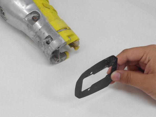
    • Remove the grey orbital button by twisting it counterclockwise.

  2. Ryobi P517 Trigger Replacement: stap 2, afbeelding 1 van 1
    • Remove the rubber boot from the device by peeling it from back to front.

  3. Ryobi P517 Trigger Replacement: stap 3, afbeelding 1 van 1
    • Flip the saw so its right side is facing up.

    • Remove the 10 mm screw using a Torx T27H screwdriver.

  4. Ryobi P517 Trigger Replacement: stap 4, afbeelding 1 van 1
    • Grab the black shoe assembly and pull it out from the front of the saw.

  5. Ryobi P517 Trigger Replacement: stap 5, afbeelding 1 van 2 Ryobi P517 Trigger Replacement: stap 5, afbeelding 2 van 2
    • Remove the two 12.5 mm screws from the front of the guide plate using the Torx T10H screwdriver.

    • Then remove the guide plate.

  6. Ryobi P517 Trigger Replacement: stap 6, afbeelding 1 van 1
    • Flip the saw so its right side is facing up.

    • Use the Torx T15H screwdriver to remove the eleven 18.1 mm screws from the housing assembly.

  7. Ryobi P517 Trigger Replacement: stap 7, afbeelding 1 van 2 Ryobi P517 Trigger Replacement: stap 7, afbeelding 2 van 2
    • Refer to the diagram provided to identify the gear case.

    • Use a Torx T15H screwdriver to remove the four 30.7 mm screws that are holding the housing assembly with the gear case assembly and gear case cover.

  8. Ryobi P517 Trigger Replacement: stap 8, afbeelding 1 van 2 Ryobi P517 Trigger Replacement: stap 8, afbeelding 2 van 2
    • Pull apart the two sides of the housing.

    • If the housing assembly does not come apart easily, do not try to force the pieces apart or else you may damage it. Ensure that all screws have been removed.

  9. Ryobi P517 Trigger Replacement: stap 9, afbeelding 1 van 2 Ryobi P517 Trigger Replacement: stap 9, afbeelding 2 van 2
    • Refer to the diagram on the device page to locate the trigger-switch, circuit board, and contact plate assembly. Each of these parts is connected by wires.

    • Remove the switch, circuit board, and contact plate holder assembly from the housing assembly.

    • Gently remove the switch by taking out the wiring from the assembly. Rough handling of the wiring could damage it and require it to be replaced.

  10. Ryobi P517 Trigger Replacement: stap 10, afbeelding 1 van 2 Ryobi P517 Trigger Replacement: stap 10, afbeelding 2 van 2
    • Lift and remove the gear case from the housing assembly and ensure that there are no parts remaining in housing assembly.

    • Ensuring the motor remains attached to the gear case to ease reassembly.

  11. Ryobi P517 Trigger Replacement, Trigger: stap 11, afbeelding 1 van 2 Ryobi P517 Trigger Replacement, Trigger: stap 11, afbeelding 2 van 2
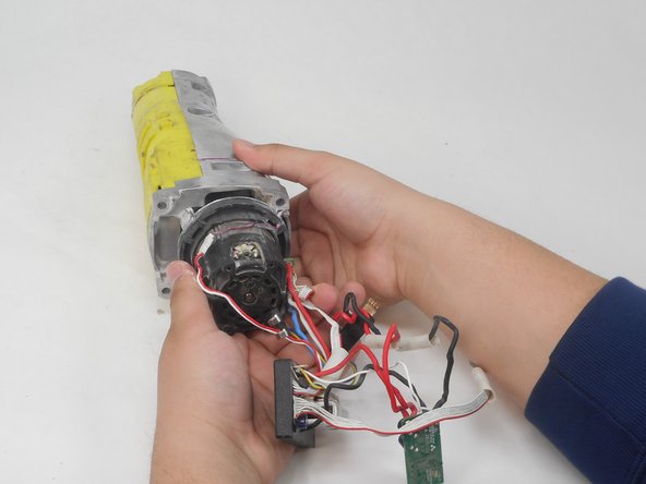
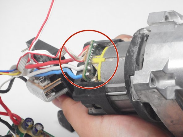
    • Position the saw so the ports connecting the circuit board assembly to the motor are accessible.

  12. Ryobi P517 Trigger Replacement: stap 12, afbeelding 1 van 1
    • Use the soldering iron and desoldering pump to desolder the circuit board assembly from the motor.

    • Be extremely careful with soldering iron. Improper use of the iron could damage the device and could lead to bodily harm.

  13. Ryobi P517 Trigger Replacement: stap 13, afbeelding 1 van 2 Ryobi P517 Trigger Replacement: stap 13, afbeelding 2 van 2
    • Gently pull the thin red and white wire on opposite ends of its connector to disconnect the LED from the circuit board.

Conclusie

To reassemble your device, follow these instructions in reverse order.

Abner Fernandez

Lid sinds: 02/15/24

445 Reputatie

4 handleidingen geschreven

0 opmerkingen

Voeg opmerking toe

Weergavestatistieken:

Afgelopen 24 uren: 0

Afgelopen 7 dagen: 2

Afgelopen 30 dagen: 5

Altijd: 33