Deze versie kan foutieve bewerkingen bevatten. Schakel over naar de recentste gecontroleerde momentopname.
Wat je nodig hebt
-
Deze stap is niet vertaald. Help het te vertalen
-
Unscrew 4 screws on top of camera.
-
Unscrew 4 screws on bottom of camera. (Picture 2)
-
When all 8 screws are out, remove front and back cover from camera.
-
-
Deze stap is niet vertaald. Help het te vertalen
-
Remove this piece located on the right side of the camera.
-
This piece can by removed by lightly pulling off of the camera.
-
-
Deze stap is niet vertaald. Help het te vertalen
-
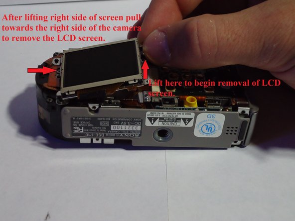
Begin by removing the small piece of black foam located at the top right of the LCD screen. (Picture 1)
-
Remove screw which is located exactly where the black foam was. (Picture 1)
-
After screw is removed lift right side of LCD screen straight upward and pull to towards the right side of the camera. (Picture 2)
-
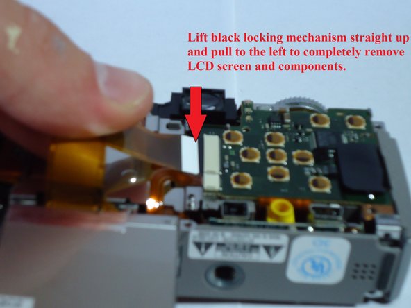
The LCD screen will pull out of the camera and 2 ribbon circuits will need to be detached.
-
Detach both by carefully pulling out of black locking mechanism. (Picture 3)
-
-
Deze stap is niet vertaald. Help het te vertalen
-
Remove the three screws holding the metal backing down. (Picture 1)
-
Push on the plastic piece near the top right of the metal backing and lift the backing up to release the top half. (Picture 2)
-
Pull the metal backing towards the bottom of the camera to free it from the lower right catch. (Picture 3)
-
Lift the metal backing up and off of the camera.
-
-
Deze stap is niet vertaald. Help het te vertalen
-
Disconnect the two ribbon circuits on the front of the camera.
-
The camera should now be in two parts. Set the lens half off to the side and continue working with the side containing the flash.
-
-
-
Deze stap is niet vertaald. Help het te vertalen
-
Lift the left side of the bottom panel towards the top of the camera.
-
Then pull the panel down and away from the camera.
-
-
Deze stap is niet vertaald. Help het te vertalen
-
Remove the screw at the upper right corner. (Picture 1)
-
Carefully work the ribbon circuit, pictured at the left side, back and forth to free it from the plastic retainer. (Picture 1)
-
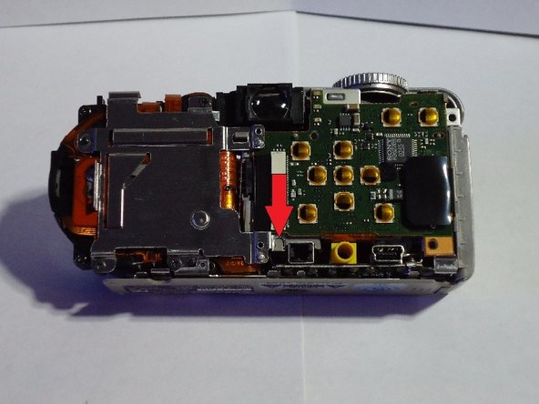
Lift the black locking mechanism up (Picture 2) and gently pull the ribbon circuit to detach.
-
Upon completion of this step, the lower circuit board should be attached in one place and be freely hanging as shown. (Picture 2)
-
-
Deze stap is niet vertaald. Help het te vertalen
-
Remove upper left ribbon circuit by lifting black locking flap and gently pulling out.
-
Remove the lower right ribbon circuit by gently pulling out.
-
Remove the lower left screw.
-
-
Deze stap is niet vertaald. Help het te vertalen
-
Remove the three screws securing the rear circuit board.
-
Lift up on the left side of the circuit board and gently pull to the left to dislodge.
-
-
Deze stap is niet vertaald. Help het te vertalen
-
Gently lift the rear circuit board away from the camera.
-
Rotate the circuit board 180 degrees so that it is directly below the camera.
-
Now gently remove the front circuit board and rotate both the rear and front circuit boards 180 degrees so that they are directly above the camera (picture 2).
-
-
Deze stap is niet vertaald. Help het te vertalen
-
Lift the black locking mechanism up and gently pull the ribbon circuit free.
-
Remove the wires by using a tweezers to grasp the white plastic plug and pull gently until free.
-
Note: The wires shown by the red circle are connected on the opposite side as the ribbon circuit.
-
-
Deze stap is niet vertaald. Help het te vertalen
-
Using the tip of the tweezers, press on the latching mechanisms one at a time to free the flash housing piece.
-
Once the flash housing piece is free gently pull up to remove.
-
Note: You may have to wiggle the flash housing back and forth to free the circuit board located on the bottom of the flash housing
-
-
Deze stap is niet vertaald. Help het te vertalen
-
Remove the tape to release the top half.
-
The Half with the circuit board is the built-in flash.
-
You have successfully removed the built in flash!!
-


Annuleren: ik heb deze handleiding niet afgemaakt.
Één andere persoon heeft deze handleiding voltooid.
Team

UW Stout, Team 1-1, Zhou Fall 2011 Lid van UW Stout, Team 1-1, Zhou Fall 2011
UWSTOUT-ZHOU-F11S1G1
5 Leden
3 handleidingen geschreven