Deze versie kan foutieve bewerkingen bevatten. Schakel over naar de recentste gecontroleerde momentopname.
Wat je nodig hebt
-
Deze stap is niet vertaald. Help het te vertalen
-
Use your thumbs to push the two battery retaining tabs away from the battery.
-
The battery should pop up enough to rotate it toward yourself and lift it out of the lower case.
-
-
Deze stap is niet vertaald. Help het te vertalen
-
Remove the three 2.3 mm Phillips screws securing the memory cover to the lower case.
-
-
Deze stap is niet vertaald. Help het te vertalen
-
Lift the memory cover slightly and pull it toward yourself to remove it from the lower case.
-
-
Deze stap is niet vertaald. Help het te vertalen
-
Remove the following ten screws:
-
Two 14.7 mm shouldered Phillips.
-
Three 12.3 mm Phillips.
-
One 3.8 mm T8 Torx.
-
One 6.8 mm T8 Torx.
-
Three 1.3 mm Phillips.
-
-
Deze stap is niet vertaald. Help het te vertalen
-
Use your fingernails to separate the ZIF cable lock away from its socket. (Move the two brown bits down 1mm)
-
-
Deze stap is niet vertaald. Help het te vertalen
-
Use the tip of a spudger to slide the trackpad ribbon cable out of its socket.
-
-
Deze stap is niet vertaald. Help het te vertalen
-
Remove the four 3.4 mm Phillips screws from the PC card side of the PowerBook.
-
-
Deze stap is niet vertaald. Help het te vertalen
-
Remove the four 3.4 mm Phillips screws from the DVI connector side of the PowerBook.
-
-
Deze stap is niet vertaald. Help het te vertalen
-
Depress the display latch release button and open your display.
-
-
Deze stap is niet vertaald. Help het te vertalen
-
Starting near the display, lift the upper case straight up off the lower case, minding any cables that may get caught.
-
-
Deze stap is niet vertaald. Help het te vertalen
-
If necessary, peel back the strip of aluminum tape covering the modem cable.
-
-
Deze stap is niet vertaald. Help het te vertalen
-
Use the flat end of a spudger to pry the modem cable connector up off the modem.
-
-
Deze stap is niet vertaald. Help het te vertalen
-
Use a 4 mm nut driver to remove the two nuts securing the modem to the PC card cage.
-
-
Deze stap is niet vertaald. Help het te vertalen
-
Lift the modem straight up off the studs on the PC card cage.
-
-
Deze stap is niet vertaald. Help het te vertalen
-
Use the flat end of a spudger to pry the hard drive cable connector up off the logic board.
-
Bend the hard drive cable away from the PC card cage, giving yourself room to remove it.
-
-
Deze stap is niet vertaald. Help het te vertalen
-
Use the flat end of a spudger to pry the PC card cage connector up off the logic board.
-
-
Deze stap is niet vertaald. Help het te vertalen
-
Use the tip of a spudger to peel back the small strip of copper tape off the edge of the PC card cage near the side of the lower case.
-
-
Deze stap is niet vertaald. Help het te vertalen
-
Remove the four Phillips screws (2- 4 mm & 2 -6.8 mm ) securing the PC card cage to the lower case.
-
-
Deze stap is niet vertaald. Help het te vertalen
-
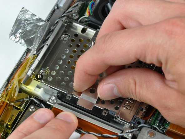
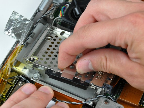
Lift the PC card cage by its center piece and maneuver it out of the lower case.
-
-
Deze stap is niet vertaald. Help het te vertalen
-
Use the flat end of a spudger to pry the ribbon cable connector up off the AirPort/Bluetooth board.
-
-
Deze stap is niet vertaald. Help het te vertalen
-
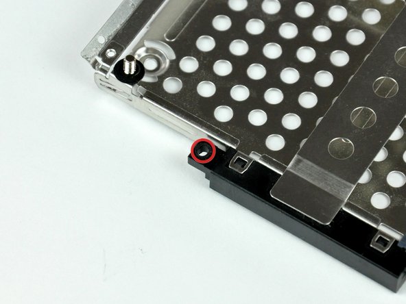
Remove the single 2.1 mm Phillips screw securing the AirPort/Bluetooth bracket to the lower case.
-
-
-
Deze stap is niet vertaald. Help het te vertalen
-
Use the flat end of a spudger to pry the AirPort/Bluetooth board up off the adhesive securing it to the lower case.
-
-
Deze stap is niet vertaald. Help het te vertalen
-
If necessary, remove the piece of tape and EMI foam covering the AirPort/Bluetooth antennas.
-
-
Deze stap is niet vertaald. Help het te vertalen
-
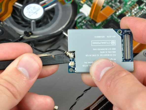
Use the flat end of a spudger to pry both antenna connectors up off the AirPort/Bluetooth board.
-
-
Deze stap is niet vertaald. Help het te vertalen
-
Pull the display data cable away from its socket to disconnect it from the logic board.
-
-
Deze stap is niet vertaald. Help het te vertalen
-
If necessary, use the tip of a spudger to remove the small piece of foam tape from the side of the left speaker.
-
-
Deze stap is niet vertaald. Help het te vertalen
-
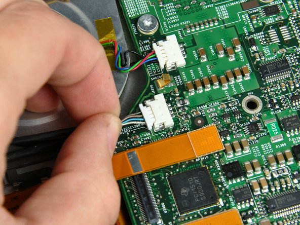
Disconnect the inverter cable from the logic board.
-
-
Deze stap is niet vertaald. Help het te vertalen
-
De-route both AirPort/Bluetooth antennas and the inverter cable from underneath the DC-in board ribbon cable.
-
-
Deze stap is niet vertaald. Help het te vertalen
-
Remove four T6 Torx screws from the left display hinge. 2- 8 mm and 1 -10 mm and one 6 mm left to right.
-
-
Deze stap is niet vertaald. Help het te vertalen
-
Remove four T6 Torx screws from the right display hinge. 2- 8 mm and 1 -10 mm and one 6 mm right to left.
-
-
Deze stap is niet vertaald. Help het te vertalen
-
While supporting the display with one hand, remove the one remaining T6 10 mm Torx screw from each display bracket (two screws total).
-
-
Deze stap is niet vertaald. Help het te vertalen
-
Lift the display straight up from the lower case, minding any cables that may get caught.
-
-
Deze stap is niet vertaald. Help het te vertalen
-
A small bracket (shown in red) near either side of the clutch cover is free to rotate about the display hinge and must be inserted behind the heat sink framework for the display to seat properly.
-
Before completely lowering the display onto the lower case, use a spudger to rotate the bracket toward the rear edge of your PowerBook, and insert the bracket between the heat sink framework and the adjacent spring. The second picture shows the bracket correctly installed.
-
When removing the display screws, keep track of the thin metal bracket (shown in green) under the screws on the inner display bracket.
-
The outer display bracket (shown in orange) simply slides onto the spiral display spring. Be sure to press it on before installing your display into the lower case.
-
-
Deze stap is niet vertaald. Help het te vertalen
-
Remove the single Phillips screw from the lower left and right corners of the display.
-
-
Deze stap is niet vertaald. Help het te vertalen
-
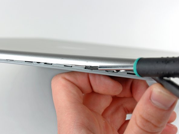
Insert the flat end of a spudger between the front display bezel and the plastic rim attached to the rear bezel near the lower right corner of the display.
-
While carefully prying the rear display bezel away from the display assembly, use a small flathead screwdriver to pry the small steel clip nearest the bottom right corner of the display away from the edge of the front display bezel.
-
Repeat the above procedure until you've released all the clips along the right side of the display.
-
-
Deze stap is niet vertaald. Help het te vertalen
-
Slightly lift the recently-freed corner of the rear display bezel to separate the clips along the span of the clutch hinges.
-
-
Deze stap is niet vertaald. Help het te vertalen
-
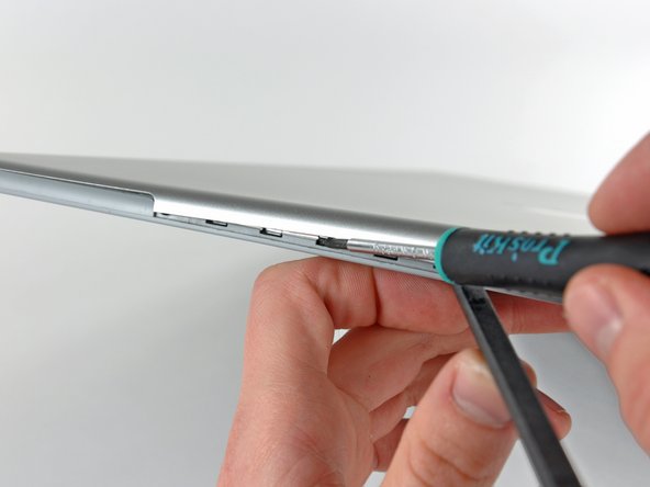
Insert the flat end of a spudger between the rear display bezel and the plastic surround of the front display bezel near the lower left corner of the display.
-
Carefully pry the rear display bezel away from the front display bezel to release a metal clip.
-
-
Deze stap is niet vertaald. Help het te vertalen
-
Repeat the previous procedure to release the clips along the left side of the rear display bezel.
-
-
Deze stap is niet vertaald. Help het te vertalen
-
Slightly lift the lower edge of the rear display bezel and push it toward the top edge of the display, releasing the clips along the top edge of the rear display bezel.
-
Remove the rear display bezel and set it aside.
-
-
Deze stap is niet vertaald. Help het te vertalen
-
Use the tip of a spudger to lift the display inverter enough to grab it with your fingers.
-
Lift the display inverter slightly out of the clutch hinges.
-
-
Deze stap is niet vertaald. Help het te vertalen
-
Disconnect the backlight cable from its socket on the display inverter.
-
-
Deze stap is niet vertaald. Help het te vertalen
-
Disconnect the display data cable from its socket on the LCD.
-
-
Deze stap is niet vertaald. Help het te vertalen
-
Remove the four 3.3 mm Phillips screws securing the right side of the LCD to the front display bezel.
-
-
Deze stap is niet vertaald. Help het te vertalen
-
Remove the three 3.3 mm Phillips screws along the top edge of the LCD.
-
-
Deze stap is niet vertaald. Help het te vertalen
-
Remove the four 3.3 mm Phillips screws along the left side of the LCD.
-
-
Deze stap is niet vertaald. Help het te vertalen
-
With the heat gun set to low, start by heating the front display bezel near the upper left corner of the display panel.
-
-
Deze stap is niet vertaald. Help het te vertalen
-
Insert a plastic opening tool between the metal LCD frame and the front bezel.
-
Use the flat end of a metal spudger to gently pry up the adhesive securing the metal LCD frame to the front bezel, taking special care not to scratch the LCD panel.
-
-
Deze stap is niet vertaald. Help het te vertalen
-
While it is still inserted between the metal LCD frame and the front bezel, run the edge of your metal spudger along the top edge of the display to separate the adhesive securing the two pieces together, heating the area you are working on with a heat gun as necessary.
-
-
Deze stap is niet vertaald. Help het te vertalen
-
Continue running the edge of your metal spudger between the LCD frame and the front bezel until the right, bottom, and left sides of the LCD are free.
-
-
Deze stap is niet vertaald. Help het te vertalen
-
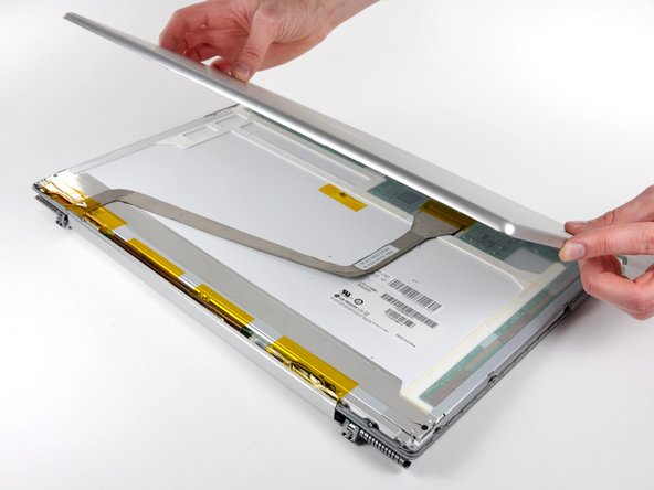
As you pull the top edge of the LCD out of the front display bezel, remove the small magnet that is responsible for putting the display to sleep when it is closed.
-
-
Deze stap is niet vertaald. Help het te vertalen
-
Lift the top edge of the LCD out of the front display bezel and slightly pull its bottom edge away from the clutch hinges.
-
-
Deze stap is niet vertaald. Help het te vertalen
-
Push the backlight cable connector through the slot cut into the front display bezel.
-
Remove the LCD.
-
-
Deze stap is niet vertaald. Help het te vertalen
-
Use the tip of a spudger to lift the display inverter enough to grab it with your fingers.
-
Lift the display inverter out of the clutch hinges.
-
-
Deze stap is niet vertaald. Help het te vertalen
-
Disconnect the inverter cable from the display inverter.
-
Remove the display inverter and set it aside.
-
-
Deze stap is niet vertaald. Help het te vertalen
-
Remove the two 10.3 mm T8 Torx screws securing the clutch hinges near the display data cable.
-
-
Deze stap is niet vertaald. Help het te vertalen
-
Remove the two 10.3 mm T8 Torx screws securing the center of the clutch hinges.
-
-
Deze stap is niet vertaald. Help het te vertalen
-
Remove the final pair of 10.3 mm T8 Torx screws securing the clutch hinges to the front display bezel.
-
-
Deze stap is niet vertaald. Help het te vertalen
-
Separate the clutch hinges from the front display bezel.
-
Use the tip of a spudger to pry the gray plastic end cap off the inverter cable side of the clutch hinges.
-
Remove the plastic end cap and set it aside.
-
-
Deze stap is niet vertaald. Help het te vertalen
-
Slide the inverter and antenna cables out of their slot in the clutch hinges.
-
-
Deze stap is niet vertaald. Help het te vertalen
-
De-route both the black and the gray antenna cables through the black plastic cable retainer attached to the inverter cable.
-
-
Deze stap is niet vertaald. Help het te vertalen
-
Remove the 2.7 mm Phillips screw securing the display data cable ground loop to the front display bezel.
-
-
Deze stap is niet vertaald. Help het te vertalen
-
Remove the clutch hinges (with the display data cable still attached) from the front display bezel.
-