Deze versie kan foutieve bewerkingen bevatten. Schakel over naar de recentste gecontroleerde momentopname.
Wat je nodig hebt
-
Deze stap is niet vertaald. Help het te vertalen
-
Use a coin or a spudger to turn the battery locking screw 90 degrees clockwise.
-
Lift the battery out of the computer.
-
-
Deze stap is niet vertaald. Help het te vertalen
-
Remove the four Phillips screws from the memory door.
-
Slide the memory door away from the memory compartment.
-
-
Deze stap is niet vertaald. Help het te vertalen
-
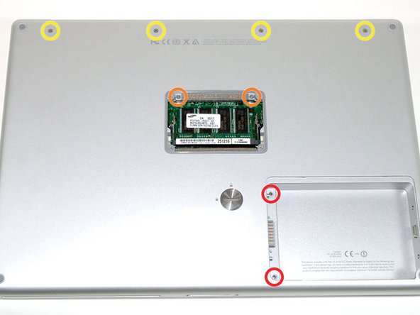
Remove the following 8 screws:
-
Two 3 mm Phillips in the battery compartment, on either side of the battery contacts.
-
Two 12 mm Phillips on either side of the memory compartment.
-
Four 16 mm Phillips along the hinge.
-
-
Deze stap is niet vertaald. Help het te vertalen
-
Rotate the computer 90 degrees clockwise, so that the power receptacle faces you.
-
Remove the three 3 mm Phillips screws.
-
-
Deze stap is niet vertaald. Help het te vertalen
-
Turn the computer 90 degrees clockwise so that the hinge faces you.
-
Remove the bottom 5 mm Phillips screw on either side of the hinge (two total).
-
-
Deze stap is niet vertaald. Help het te vertalen
-
Rotate the computer 90 degrees clockwise, so that the ports face you.
-
Remove the three 3 mm Phillips screws.
-
-
Deze stap is niet vertaald. Help het te vertalen
-
Turn the computer over and open the display.
-
Remove the two 1.5 mm hex screws in either corner, next to the display (a T6 Torx driver will work, but repeated use will strip the screws).
-
-
Deze stap is niet vertaald. Help het te vertalen
-
Grasp the back corners of the upper case and pull up. Do not pull the upper case off yet; you still need to disconnect the keyboard and trackpad cable.
-
Lift the back of the case up and work your fingers along the sides, freeing the case as you go. Once you have freed the sides, you may need to rock the case up and down to free the front of the upper case.
-
-
Deze stap is niet vertaald. Help het te vertalen
-
Rotate the upper case up and toward the screen, so that the upper case rests against it.
-
-
Deze stap is niet vertaald. Help het te vertalen
-
Remove the orange tape securing the trackpad ribbon to the logic board.
-
Disconnect the trackpad ribbon from the logic board.
-
Remove the upper case from the computer.
-
-
Deze stap is niet vertaald. Help het te vertalen
-
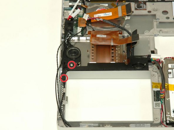
Remove the 9.5 mm silver Phillips screw from the top of the right ambient light sensor board.
-
Remove the small 3 mm black Phillips screw from the bottom of the board.
-
-
Deze stap is niet vertaald. Help het te vertalen
-
Lift the right ambient light sensor board Straight up from the Logic Board.
-
-
Deze stap is niet vertaald. Help het te vertalen
-
Remove the two black Phillips screws from the right speaker.
-
Lift the speaker away from the logic board and place it aside
-
-
Deze stap is niet vertaald. Help het te vertalen
-
Use your fingernail to flip up the black plastic flap locking the modem cable in place.
-
Slide the modem cable from its connector.
-
-
Deze stap is niet vertaald. Help het te vertalen
-
Disconnect the 13 indicated cables, removing tape as necessary.
-
-
-
Deze stap is niet vertaald. Help het te vertalen
-
Remove the following 8 Phillips screws from the logic board:
-
Three 6.5 mm in the upper left corner.
-
Five 4.5 mm around the edges.
-
-
Deze stap is niet vertaald. Help het te vertalen
-
Use a spudger to gently (very gently) pry up the left side of the logic board.
-
-
Deze stap is niet vertaald. Help het te vertalen
-
Disconnect the DC-In connector from the left side of the logic board.
-
-
Deze stap is niet vertaald. Help het te vertalen
-
Disconnect the battery cable from the front, left corner of the logic board.
-
-
Deze stap is niet vertaald. Help het te vertalen
-
Grasp the logic board at the left edge with one hand and at the thinnest section with the other hand. Lift the left edge of the board up to approximately a 30 degree angle (if you don't have your protractor handy, just lift until the DVI port clears the right hinge).
-
Once the logic board clears the ports, slide it out to the left.
-
-
Deze stap is niet vertaald. Help het te vertalen
-
To properly reassemble your PowerBook, you'll have to clean off and replace the old thermal compound. Use our Applying Thermal Paste Guide to prepare the processor and heat sink surfaces.
-
-
Deze stap is niet vertaald. Help het te vertalen
-
Use a firm plastic edge to scrape the thermal material off the processor.
-
-
Deze stap is niet vertaald. Help het te vertalen
-
Remove the two 3 mm black Phillips screws from the left ambient light sensor board.
-
Lift the left ambient light sensor board out of the computer, removing tape as necessary.
-
-
Deze stap is niet vertaald. Help het te vertalen
-
Deroute the Bluetooth and RJ-11 cables from around the left side of the speaker.
-
-
Deze stap is niet vertaald. Help het te vertalen
-
Disconnect the speaker cable from the DC/Sound card.
-
-
Deze stap is niet vertaald. Help het te vertalen
-
Remove the 4 mm hex nut from below the left speaker.
-
Remove the 3 mm black Phillips screw from bottom left corner of the speaker assembly, to the left of the battery compartment.
-
-
Deze stap is niet vertaald. Help het te vertalen
-
Lift the speaker assembly (including the right speaker) out of the computer.
-
-
Deze stap is niet vertaald. Help het te vertalen
-
Remove the two 4.2 mm silver Phillips screws from the left corners of the PC card cage.
-
-
Deze stap is niet vertaald. Help het te vertalen
-
Lift the PC card cage up and remove it from the computer.
-
-
Deze stap is niet vertaald. Help het te vertalen
-
Remove the two 4.2 mm silver Phillips screws from either side of the large orange Airport ribbon.
-
-
Deze stap is niet vertaald. Help het te vertalen
-
Lift the Airport card out of the computer and slide a spudger between the card and the antenna connector to disconnect the cable from the card.
-
Deroute the antenna cable from the side of the card, removing tape as necessary.
-
You don't need to remove the Airport card entirely. We're just trying to free up the Airport antenna cable.
-
-
Deze stap is niet vertaald. Help het te vertalen
-
Using a spudger, pry up the Bluetooth board from the cavity in front of the battery compartment.
-
-
Deze stap is niet vertaald. Help het te vertalen
-
Disconnect the Bluetooth antenna cable from the Bluetooth board.
-
-
Deze stap is niet vertaald. Help het te vertalen
-
Close the display and turn the hinge side of the computer to face you.
-
Remove the remaining Phillips screw on either side of the hinge (two screws total).
-
-
Deze stap is niet vertaald. Help het te vertalen
-
Open the display and turn the computer so the screen faces you.
-
Remove the 10 mm T8 Torx screw closer to the display on either side of the hinge (two screws total).
-
-
Deze stap is niet vertaald. Help het te vertalen
-
Remove the longer 13 mm shouldered T8 Torx screw remaining on either hinge (two screws total).
-
-
Deze stap is niet vertaald. Help het te vertalen
-
Remove the following 7 Phillips screws from the heat sink:
-
Four 4 mm silver screws.
-
Two 5 mm black screws.
-
One 9 mm silver screw in the upper left corner of the left fan.
-
-
Deze stap is niet vertaald. Help het te vertalen
-
Remove the heat sink from the case, minding the left corner, as it tends to catch in the case (the fans will come out with the heat sink).
-
-
Deze stap is niet vertaald. Help het te vertalen
-
Disconnect the 4-pin power cable and orange ribbon cable from the DC/Sound card.
-
-
Deze stap is niet vertaald. Help het te vertalen
-
Remove the T8 Torx screw from the RJ-11 board.
-
Remove the 5 mm standoff that secures the DC/Sound card to the lower case using a nut driver or pliers.
-
-
Deze stap is niet vertaald. Help het te vertalen
-
Lift the DC/Sound card out of the computer and turn it over.
-
Disconnect the Bluetooth cable from the DC/Sound card, removing tape as necessary.
-
-
Deze stap is niet vertaald. Help het te vertalen
-
Use your thumbs to slide the RJ-11 board away from the sound card in the same direction you would disconnect a cable. This is your chance to get out some aggression, as the board will most likely be very tight and requires a good deal of force to remove. Don't get carried away though - don't hold onto the power connector and don't put too much actual force on the card itself.
-
The DC/Sound card should now be free.
-


Annuleren: ik heb deze handleiding niet afgemaakt.
16 andere personen hebben deze handleiding voltooid.
Bijgevoegde documenten

3 opmerkingen
The Tools Used list specifies a #6 Torx wrench, but in step 7 it says a 1.5mm hex wrench is preferred. This is good to know ahead of time since a #6 Torx wrench is not available from the local hardware store, but a 1.5mm hex wrench is.
Thermal paste is required for reassembly at step 17.
I follow the instruction to open the box, but you don't have to take the whole computer apart to get to the part. You can work on the side where the part is and it is much more easier. The chance of breaking a wire is less likely. I recommend that once the box is open and the mainboard is exposed, that the person on unscrew the left speakers, remove the screw near the small left speaker. Remove the screws that secure the PC Card tray, remove the tray. Remove the screws that secure the electronic eye to the top left, remove the screw that secure the dc board and the parts is ready to come out.
Agreed - I just removed the DC/sound board without touching the logic board! very happy =)
JP
Jesal -