Deze versie kan foutieve bewerkingen bevatten. Schakel over naar de recentste gecontroleerde momentopname.
Wat je nodig hebt
-
Deze stap is niet vertaald. Help het te vertalen
-
Use a coin to turn the battery locking screw 90 degrees to the right.
-
Lift the battery out of the computer.
-
-
Deze stap is niet vertaald. Help het te vertalen
-
Open the computer and rotate the display as far as possible.
-
Remove the T6 Torx screw from the bottom left corner of the display assembly. The computer casing will not allow the screwdriver to be inserted directly into the screw, so be careful not to strip the screw.
-
-
Deze stap is niet vertaald. Help het te vertalen
-
Remove the T6 Torx screw from the bottom right corner of the display assembly.
-
-
Deze stap is niet vertaald. Help het te vertalen
-
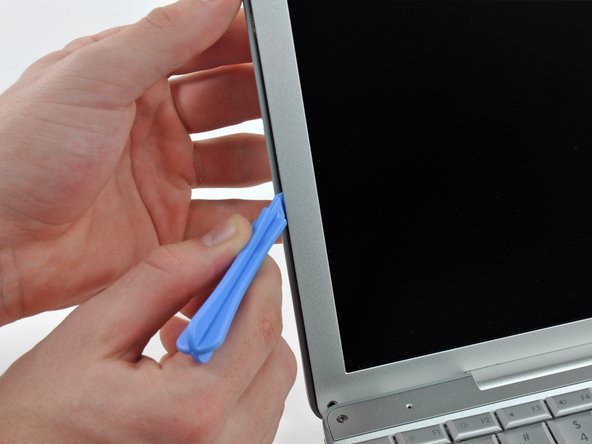
Insert a plastic opening tool between the left edge of the front display bezel and the plastic strip attached to the rear bezel, with the edge of the tool angled toward the LCD.
-
Rotate the tool away from the LCD to pop the rear bezel off the tabs on the front display bezel.
-
Work along the left edge of the display until the rear bezel is evenly separated from the front bezel.
-
-
Deze stap is niet vertaald. Help het te vertalen
-
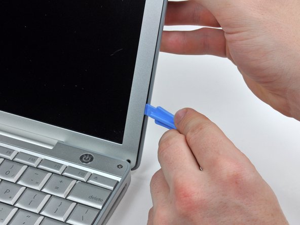
Insert a plastic opening tool between the right edge of the front display bezel and the plastic strip attached to the rear bezel, with the edge of the tool angled toward the LCD.
-
Rotate the tool away from the LCD to pop the rear bezel off the tabs on the front display bezel.
-
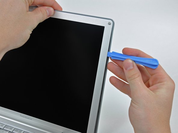
Work along the right edge of the display until the rear bezel is evenly separated from the front bezel.
-
-
Deze stap is niet vertaald. Help het te vertalen
-
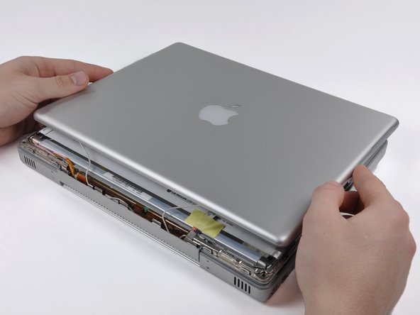
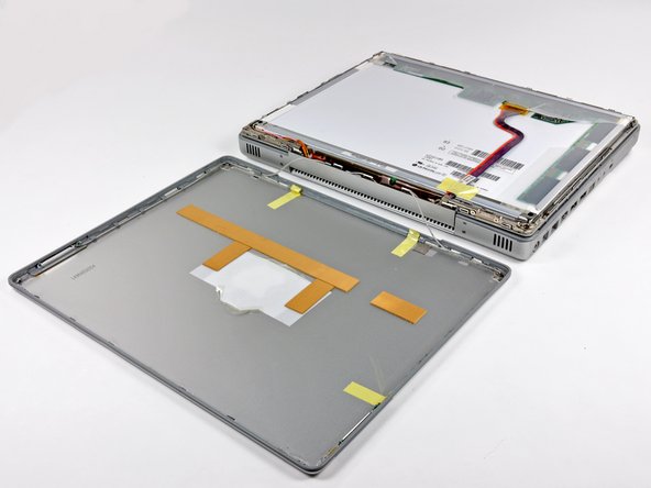
Close the display.
-
Lift the bottom edge of the rear display bezel up about an inch.
-
Slide the rear display bezel forward to release the clips along the top edge of the display.
-
Rotate the rear display bezel away from the display and lay it next to the computer.
-
-
Deze stap is niet vertaald. Help het te vertalen
-
Remove the Phillips screw securing the inverter board.
-
-
Deze stap is niet vertaald. Help het te vertalen
-
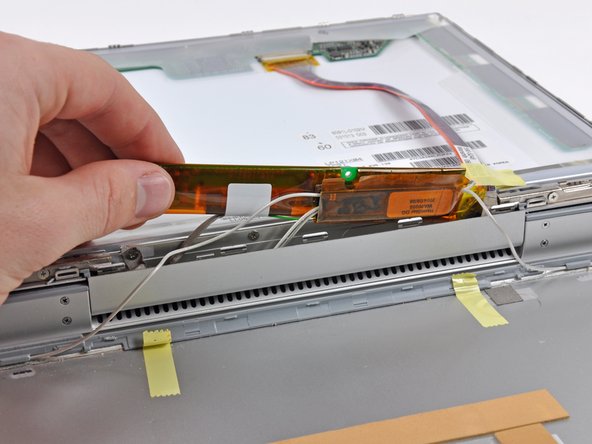
Insert the pointed end of the a spudger between the protective tape and the inverter board.
-
Carefully pull up with the spudger to lift the inverter board out enough to access the connector cables.
-
Once you can easily grab the board, pull it up enough to gain access to the inverter board's output connector.
-
-
-
Deze stap is niet vertaald. Help het te vertalen
-
Disconnect the cable by pulling the connector away from the inverter board's socket.
-
-
Deze stap is niet vertaald. Help het te vertalen
-
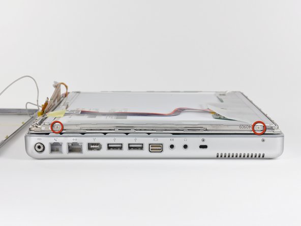
Remove the two Phillips screws from both sides of the display (four in total).
-
-
Deze stap is niet vertaald. Help het te vertalen
-
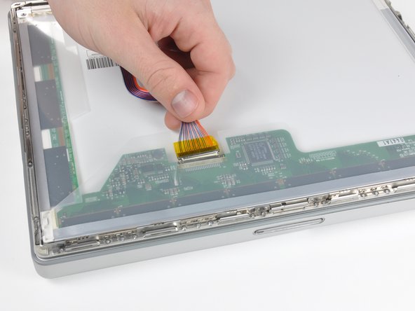
Remove any tape on the display data cable.
-
Pull the display data cable connector away from its socket to disconnect it from the LCD.
-
-
Deze stap is niet vertaald. Help het te vertalen
-
Open the display slightly.
-
Push the LCD away from the front display bezel near its top edge.
-
Remove the LCD, being wary of any cables that may get caught
-
-
Deze stap is niet vertaald. Help het te vertalen
-
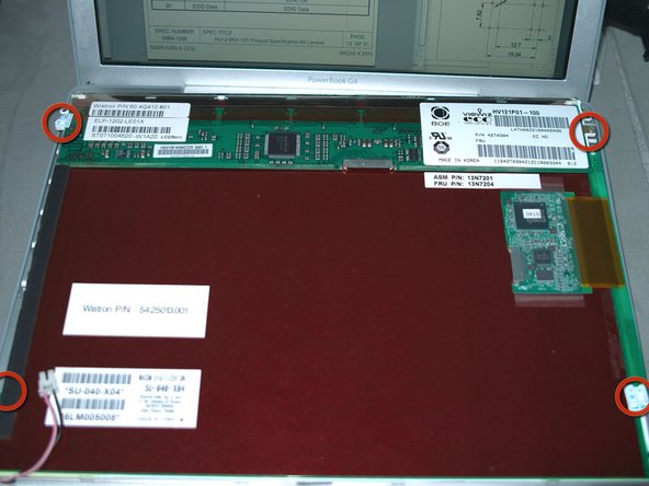
Some HV121P01 are IBM/Lenovo/Thinkpad parts. Comes with Wacom Digitizer and front shield. Remove the Wacom Digitizer first.
-
1. remove the 4 philips screws in red circles.
-
2. use some thin object, like a knife, to separate the 2 double sided tapes in red rectangles from the white plastic back.
-
The front shield can protect the screen during the following steps, remove it only after anything else are done!
-
-
Deze stap is niet vertaald. Help het te vertalen
-
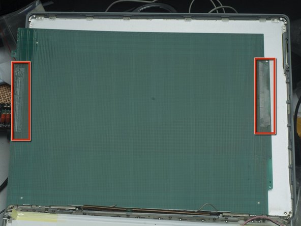
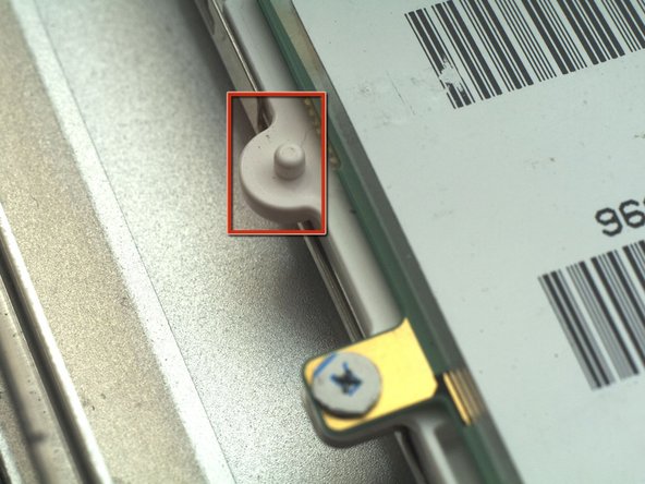
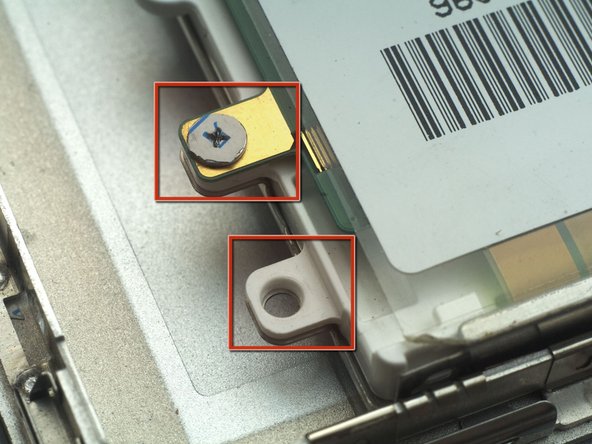
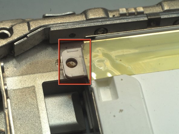
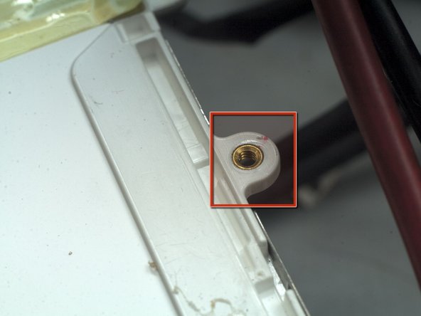
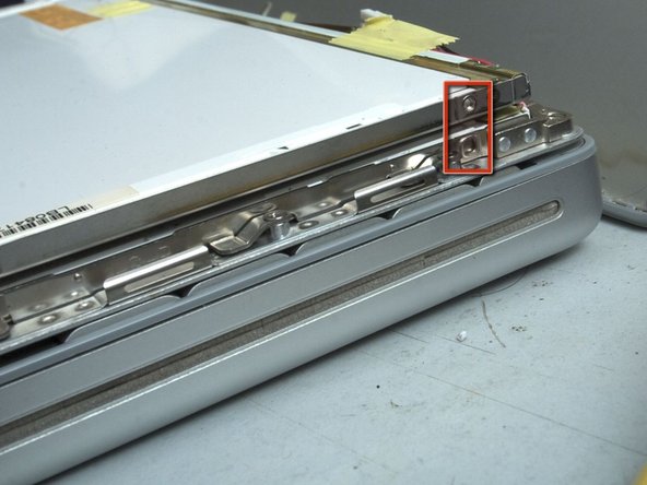
Lift 2 ends of tape,at the CCFL side, and remove 2 black philips screws in the red circles.
-
Remove the 2 small metal parts in the red rectangles.
-
-
Deze stap is niet vertaald. Help het te vertalen
-
You need to extend the CCFL High Voltage cable, if it is not long enough to reach the inverter. You'd better get a electronics friend to help you. Should be very easy for him. If it's done wrong. Leakage or shock may happen.
-
Please measure and calculate the cable length precisely. There is not enough space for wires which are too long. In this pic, they ARE 25mm/1" longer than needed. Reworking them is painful.
-
-
Deze stap is niet vertaald. Help het te vertalen
-
Remove all the extra parts from the PCB, metal frame, and white plastic back. There are 9 of them. Use knife or other cutting tool to cut the plastic. Use cutting tool to cut PCB. Use Diamond impregnated files to cut the metal frame. It's very hard and stiff, you cannot cut it with knife or wire cutters. Or, you may hurt you tool or even the LCD GLASS!! That's a game over"
-
Please be ALWAYS VERY CAREFUL and patient, DO NOT HURT the citcuit or the LCD glass (through the entire upgrade).
-
Smooth all sharp metal edges. Should be 6 of them.
-
After this step, your HV121P01 will look more like the original LCD panel i.e. IAXG01B
-
-
Deze stap is niet vertaald. Help het te vertalen
-
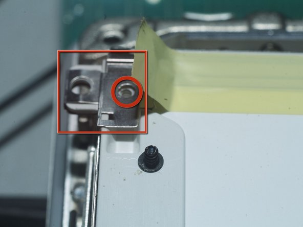
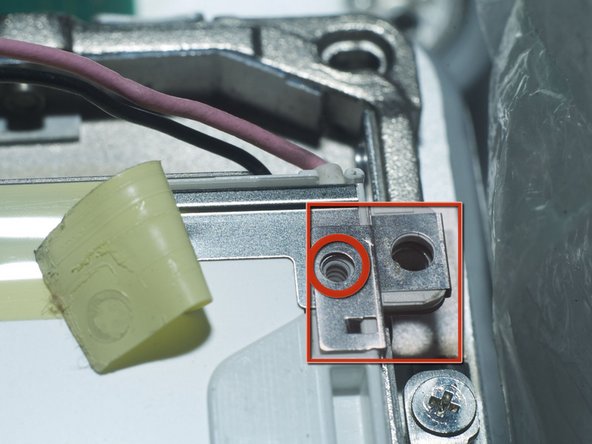
Drill four 1.5mm~2mm(1/16"~5/64") diameter, 3mm(1/8") deep holes at the left and right side of panel at the position corresponding to original LCD panel. Do NOT drill the glass!!.
-
2 will be drilled on metal and then plastic, 2 on plastic. As said before, the metal is very hard! use high quality drill and be patient and avoid overheating, or you'll burn your hand or the plastic and LCD glass.
-
In these pics, the upper LCD is the original one, the bottom one is HV121P01.
-
-
Deze stap is niet vertaald. Help het te vertalen
-
Remove the front shield, if any. It's positioned by double sided tape. Should not be very tight. But, still, be very careful about the LCD glass. if you have to break some thing, it should be the shield or tape.
-
remove any tape, glue.
-
-
Deze stap is niet vertaald. Help het te vertalen
-
Apply some electric tape here, to avoid short circuit.
-
-
Deze stap is niet vertaald. Help het te vertalen
-
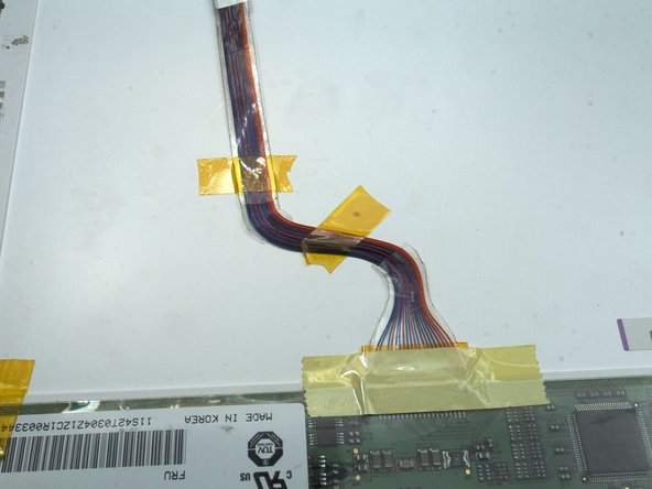
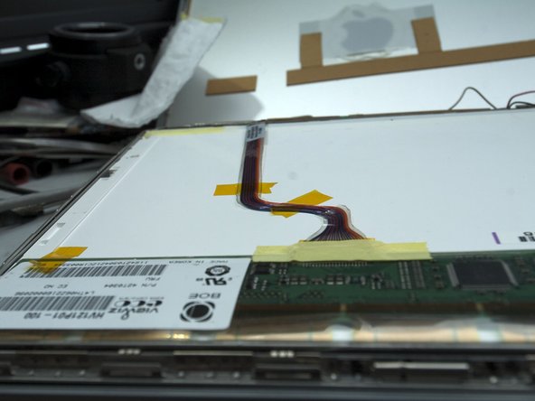
Connect the Cables.
-
The LVDS cable connector position is different. So the cable will not be flat enough. cut the transparent tape around the wires. Reposition the cable, and then using tape to hold them in position.
-
Hold the PCB with tape.
-
-
Deze stap is niet vertaald. Help het te vertalen
-
screw in 4 screws (not photoed, check LCD guide).
-
check the cable connections again. Assemble the inverter screw.
-
Power on and test. It's 1400x1050 now.
-
This might be the world's highest resolution 12" PowerBook.
-


Annuleren: ik heb deze handleiding niet afgemaakt.
7 andere personen hebben deze handleiding voltooid.
5 opmerkingen
This was a great guide!
Would something like this be compatible with a 12” iBook G4?
Tear it down and see what’s inside.
Terrance -
Hey @terrance3774, I really want to drop this panel into my 12” G4 but don’t feel like taking this task on. Do you have one already made up that I could purchase from you? Thx!