Inleiding
A common failure of the Pentax MZ-S camera is the Mirror Motor Gear. The gear drives core functions of the camera including the shutter and mirror movement. If it fails, the shutter will no longer fire and the mirror will be stuck close in the up position.
This guide explains how to disassemble the camera to access the Mirror Motor Gear as well as how to install a new gear. A general understanding of how cameras work is recommended. Some technical soldering is also required.
Wat je nodig hebt
-
-
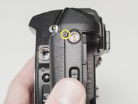
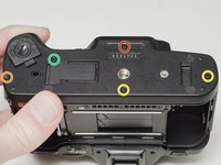
Remove two 7.5 mm #00 screws.
-
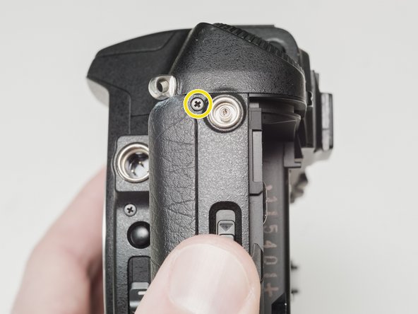
Remove one 9.0 mm #00 screw.
-
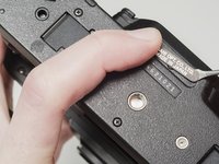
Remove one 13.5 mm #00 screw from inside the battery compartment.
-
-
-
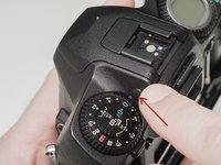
Push the button to pop up the flash.
-
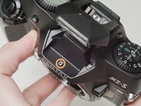
Remove one 3.5 mm #00 screw.
-
Remove one 5.5 mm #00 screw.
-
-
-
Carefully lift the top cover away from the body to access wired connections.
-
-
-
Peel back the corner of the rubber grip.
-
Remove the small plastic cover.
-
-
-
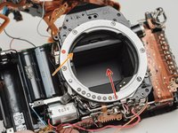
Use a 1kΩ-10kΩ high power resistor to discharge the capacitor. Place the resistor between the blue wire, exposed in the previous step, and ground.
-
-
-
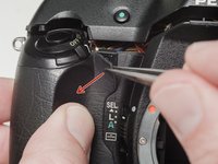
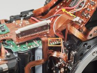
Desolder the red wire.
-
Carefully lift the sides of the white latch.
-
-
-
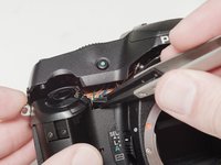
Desolder blue, black, brown and green wires.
-
Remove the loose shim washer if present.
-
-
-
Remove the piece of cellophane tape covering the flex connections.
-
Desolder flex connetions.
-
-
-
Use isopropyl alcohol to soften the adhesive under the country plate and remove.
-
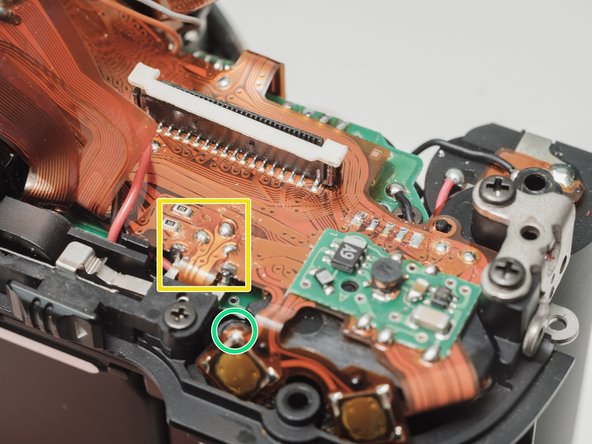
Remove one 5mm #00 screw.
-
Remove one 7.5mm #00 screw.
-
Remove two 4.5mm #00 screws.
-
Remove one 5.5mm #00 screw.
-
Remove the plastic frame around the accessory grip contacts.
-
-
-
-
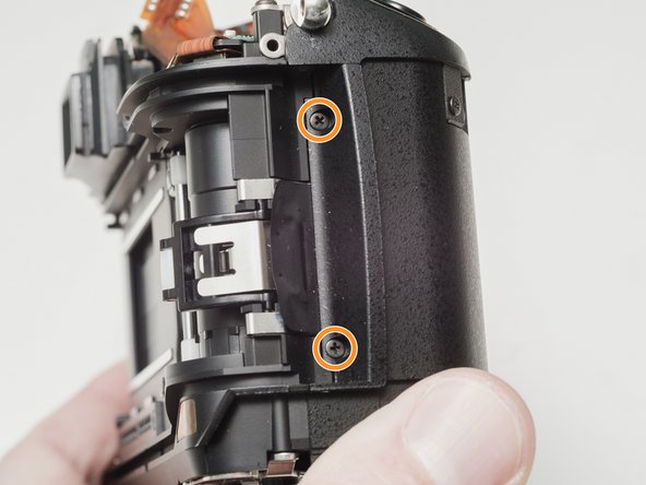
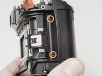
Remove one 6.0 mm #00 screw.
-
Remove two 3.5 mm #00 screws.
-
Remove one 5.0 mm #00 screw.
-
Remove the strap lug.
-
-
-
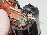
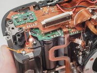
Carefully pull the right panel away from the body. It is still attached.
-
Desolder the flex connections.
-
-
-
Remove the protective mask around the accessory grip contacts.
-
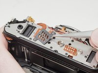
Lift the flex contacts free of their retaining posts. Use isopropyl alcohol to soften any glue or tape that is present.
-
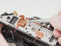
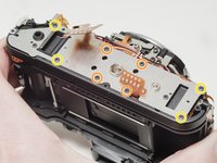
Remove four 4.0 mm #00 screws.
-
Remove four 4.0 mm #00 screws.
-
-
-
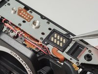
Desolder the white and pink wires.
-
Desolder the red, black and gray wires.
-
Desolder the red, black and orange wires.
-
Desolder the white and blue wires.
-
Carefully peal the tape away and detach the red, black, white and blue wires from the glue. Use isopropyl alcohol to soften the glue if necessary.
-
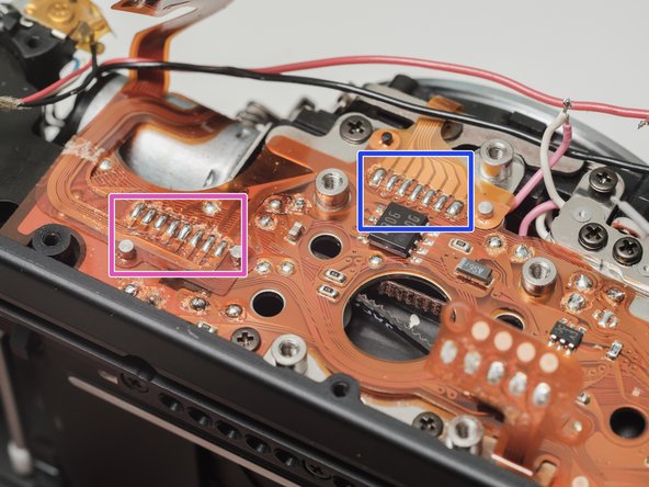
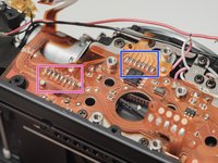
Desolder the flex connection.
-
Desolder the flex connection.
-
-
-
Desolder red, black, gray and orange wires.
-
Desolder flex contacts.
-
Disconnect flex connector.
-
-
-
Desolder black wire.
-
Desolder battery contact tab.
-
Desolder flex contacts.
-
Remove one 4.0 mm #00 screw.
-
-
-
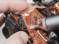
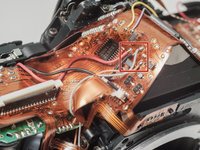
Desolder flex connection and remove from retention posts. Use isopropyl alcohol to soften the glue if necessary.
-
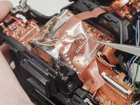
Carefully peal the flex cable from the surface of the flash capacitor. Use isopropyl alcohol to soften the glue if necessary.
-
-
-
Apply a low DC voltage (3-6 V) to the mirror motor to move the mirror to the upper position.
-
-
-
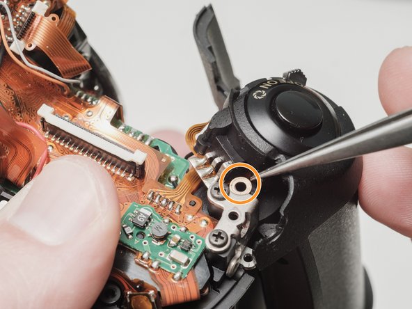
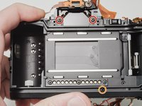
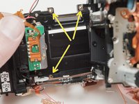
Remove two 6.5 mm #0 screws.
-
Remove one 8.0 mm #0 screw.
-
Remove one 4.0 mm #00 screw.
-
Remove one 4.5 mm #00 screw.
-
Remove two 2.5 mm #00 screws.
-
There may be a shim washer here. Remove if loose.
-
Remove one 4.0 mm #00 shoulder screw.
-
-
-
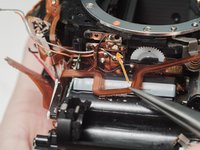
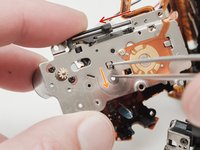
Push the mirror box up to free it from the bottom plate.
-
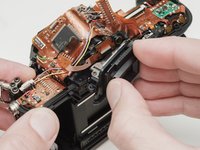
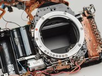
Lift the left side of the mirror box and rotate it up and out of the camera body.
-
Check for shim washers at the mount locations. Note location and remove if loose.
-
-
-
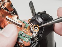
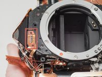
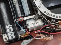
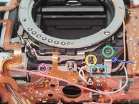
Desolder the black wire.
-
Remove one 3.0 mm #00 screw securing the mount LED.
-
Remove five 3.5 mm #00 screws.
-
-
-
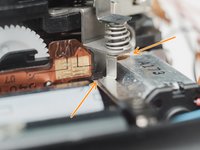
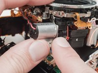
Pre-heat the brass gear to slightly expand the size of the bore.
-
Carefully but firmly press the motor shaft into the still hot gear.
-
-
-
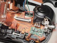
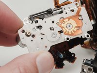
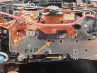
The drive gears are easily knocked loose when working in this area. Ensure that the indicated holes are aligned before beginning reassembly.
-
-
-
Install the mirror motor.
-
Slide the aperture actuator to the left.
-
Pinch the small lever downward and let it snap back into place.
-
The aperture actuator should be held in place on the left end of its travel if done correctly.
-
-
-
Install mirror motor plate.
-
Turn the black gear downward until the mirror moves to the upper position.
-
Continue turning the black gear until this hole appears in the opening and the shutter charge lever moves to the right.
-
-
-
Apply a low DC voltage (3-6 V) to the mirror motor to check the operation of the mirror box. Normal movement in the shutter blades, aperture actuator and mirror should be observable.
-


To reassemble your device, follow these instructions in reverse order. Be careful to route wires and flex cables in the way that they were originally assembled.
To reassemble your device, follow these instructions in reverse order. Be careful to route wires and flex cables in the way that they were originally assembled.
4 opmerkingen
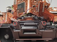
This guide is incredible :) Is there an image for Step 28? I assume those two screws are the motor mount screws. Seeing this guide makes me less worried about getting a Pentax MZ-S I've repaired EOS-1's previously using only the service manual and that seemed much more complex.
Yeah, sorry, I didn't get that pic when I did the repair. I'll try to remember when I do the next one. But you can also see the two screws in step 31, the ones on either side of the brass gear. That pic is just from after the motor has already been reinstalled. If you can do an EOS-1 you can do the MZ-S!
Would this work for mz-30? Where would I get a new gear
I would check out the replacement guide for the ZX-5n. The construction of that camera is more similar to the MZ-30. Some of the wiring will be different but just take some pics for reference when reassembling. The parts page has a link to a place where you can order the gear or you can use the gear specs to search for parts on eBay and Aliexpress.