Deze versie kan foutieve bewerkingen bevatten. Schakel over naar de recentste gecontroleerde momentopname.
Wat je nodig hebt
-
Stap 1
Voorzichtig: stappen 1-2 komen van een handleiding die in bewerking is.
Deze stap is niet vertaald. Help het te vertalen
-
Loosen the two screws on the battery panel. Then lift the panel up to remove it.
-
-
Deze stap is niet vertaald. Help het te vertalen
-
L Button.
-
Top of the battery pack.
-
To remove the battery pack, place your fingernail or a spudger at the top of the battery near the L button. Gently lift the battery out.
-
-
Deze stap is niet vertaald. Help het te vertalen
-
Two screws are hidden underneath two rubber feet highlighted in red.
-
Use the tip of a spudger to pry the rubber feet out of the lower case.
-
-
Deze stap is niet vertaald. Help het te vertalen
-
Remove the following screws securing the lower case to the body of the DSi:
-
Six 5.2 mm Phillips #00 screws.
-
One 2.7 mm Phillips #00 screw.
-
-
Deze stap is niet vertaald. Help het te vertalen
-
Insert the spudger in between the lower casing and lower panel near the top right corner of the DSi.
-
Carefully run the spudger along the edge of the outer casing, creating an opening between the body and the casing.
-
Continue running the spudger around the body of the DSi until the majority of the lower case has been separated.
-
-
-
Deze stap is niet vertaald. Help het te vertalen
-
Carefully lift the lower casing from its bottom edge.
-
Pry the volume and SD board cable up from its socket on the motherboard using a spudger.
-
Once the cable is completely removed, then you may take off the entire outer casing.
-
-
Deze stap is niet vertaald. Help het te vertalen
-
Pull the Wi-Fi board away from the motherboard by its edge closest to the headphone jack.
-
-
Deze stap is niet vertaald. Help het te vertalen
-
Pry the Wi-Fi antenna connector straight up from its socket on the Wi-Fi board.
-
-
Stap 9
Voorzichtig: stappen 9-10 komen van een handleiding die in bewerking is.
Deze stap is niet vertaald. Help het te vertalen
-
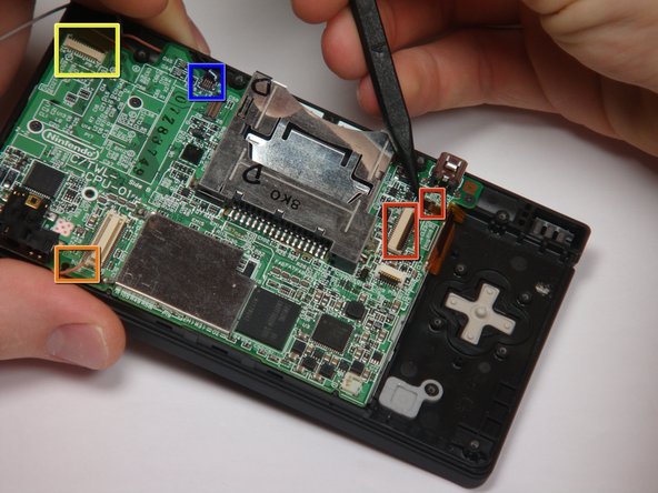
Flip up the black latch and disconnect the D-Pad/Power Button ribbon cable.
-
-
Deze stap is niet vertaald. Help het te vertalen
-
The connector is two pieces -- a white "male" piece (connected to the wires), and a beige "female" part (soldered to the main board).
-
There is a small "notch" in the female part, to give you a place to insert a small flat-head screwdriver. Put the corner of your screwdriver in there, and twist it gently to push the white part up (away from the main board). Do not try to pull it to the right (towards the battery board).
-
-
Deze stap is niet vertaald. Help het te vertalen
-
If you have not already done so, disconnect the two bottom-LCD ribbon cables from the main board by prying up the black latches and pulling the cable out to the side.
-
The ribbon cable (marked in blue) for the touch screen is particularly thin and fragile; be careful to avoid bending it more than necessary.
-
Flip up the latch and remove the touch screen cable.
-
Flip up the latch and remove the top-screen ribbon cable.
-
Pry up on the orange cable to disconnect it from the main board, much like the antenna cable on the Wi-Fi module.
-
-
Deze stap is niet vertaald. Help het te vertalen
-
Remove 4 Phillips screws from the board.
-
Lift the main board from the bottom end and flip it over to reveal the last connector.
-
-
Deze stap is niet vertaald. Help het te vertalen
-
Disconnect the ribbon cable by gently using a plastic opening tool to flip up the black connector latch. The cable should easily slide out from the connector.
-
The motherboard should now be free from the rest of the device.
-


Annuleren: ik heb deze handleiding niet afgemaakt.
2 andere personen hebben deze handleiding voltooid.
Team

Cal Poly, Team 6-1, Maness Fall 2009 Lid van Cal Poly, Team 6-1, Maness Fall 2009
CPSU-MANESS-F09S6G1
5 Leden
4 handleidingen geschreven
Één opmerking
the screwdriver needed is not a phillips #00, but a phillips #0000. I went down to Sears with my DSi and the Craftsman #00 was too large, the Craftsman #0000 (item 41645) fit perfectly, and was only two bucks