Deze versie kan foutieve bewerkingen bevatten. Schakel over naar de recentste gecontroleerde momentopname.
Wat je nodig hebt
-
Deze stap is niet vertaald. Help het te vertalen
-
Unscrew the two Phillips screws securing the battery cover to the lower case.
-
Grasp the battery cover and lift it out of the lower case.
-
-
Deze stap is niet vertaald. Help het te vertalen
-
Using a spudger tool (or your fingernail), lift up the battery from the top.
-
Grasp the battery and remove it from the DSi.
-
-
Deze stap is niet vertaald. Help het te vertalen
-
Two screws are hidden underneath two rubber feet highlighted in red.
-
Use the tip of a spudger to pry the rubber feet out of the lower case.
-
-
Deze stap is niet vertaald. Help het te vertalen
-
Remove the following screws securing the lower case to the body of the DSi:
-
Six 5.2 mm Phillips #00 screws.
-
One 2.7 mm Phillips #00 screw.
-
-
Deze stap is niet vertaald. Help het te vertalen
-
Insert the spudger in between the lower casing and lower panel near the top right corner of the DSi.
-
Carefully run the spudger along the edge of the outer casing, creating an opening between the body and the casing.
-
Continue running the spudger around the body of the DSi until the majority of the lower case has been separated.
-
-
Deze stap is niet vertaald. Help het te vertalen
-
Carefully lift the lower casing from its bottom edge.
-
Pry the volume and SD board cable up from its socket on the motherboard using a spudger.
-
Once the cable is completely removed, then you may take off the entire outer casing.
-
-
-
Deze stap is niet vertaald. Help het te vertalen
-
Pull the Wi-Fi board away from the motherboard by its edge closest to the headphone jack.
-
-
Deze stap is niet vertaald. Help het te vertalen
-
Pry the Wi-Fi antenna connector straight up from its socket on the Wi-Fi board.
-
-
Deze stap is niet vertaald. Help het te vertalen
-
Use the tip of a spudger to pry the power board connector out of its socket on the motherboard.
-
-
Deze stap is niet vertaald. Help het te vertalen
-
Use your fingernail or the edge of a plastic opening tool to flip up the retaining flap on the following three ZIF sockets:
-
Lower touchscreen cable
-
Lower LCD cable
-
Power board cable
-
After flipping up the locking tabs on all three sockets, use your fingers or a pair of tweezers to gently pull the cables straight out of their sockets.
-
-
Deze stap is niet vertaald. Help het te vertalen
-
Use your fingernail or the edge of a plastic opening tool to carefully flip up the touchscreen ribbon cable retaining flap.
-
Use the tip of a spudger to pull the touchscreen ribbon cable straight out of its socket.
-
-
Deze stap is niet vertaald. Help het te vertalen
-
Use your fingernail or the edge of a plastic opening tool to carefully flip up the dual camera ribbon cable retaining flap.
-
Use the tip of a spudger to pull the dual camera ribbon cable straight out of its socket.
-
-
Deze stap is niet vertaald. Help het te vertalen
-
With the tip of a spudger, Pry the microphone antenna up off its socket on the motherboard.
-
-
Deze stap is niet vertaald. Help het te vertalen
-
Remove the following four Phillips screws securing the motherboard to the DSi framework.
-
Three longer screws.
-
One short screw.
-
Pull the microphone and Wi-Fi antenna cables out of the notch cut into the motherboard near the headphone jack.
-
-
Deze stap is niet vertaald. Help het te vertalen
-
Slightly lift the motherboard upwards to reveal the upper LCD ribbon cable above the ABXY buttons .
-
Use your fingernail or the edge of a plastic opening tool to carefully flip up the upper LCD ribbon cable retaining flap.
-
Remove the motherboard from the DSi.
-
-
Deze stap is niet vertaald. Help het te vertalen
-
Use the tip of a spudger to pry the metal backing of the lower LCD up from the DSi's framework.
-
Lift the lower LCD assembly out of the DSi.
-
-
Deze stap is niet vertaald. Help het te vertalen
-
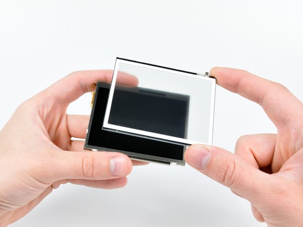
Insert the edge of a plastic opening tool between the lower touchscreen and the lower LCD.
-
Carefully run the edge of the opening tool along the perimeter of the touchscreen to detach it from the lower LCD.
-
Remove the touchscreen from the lower LCD.
-
Lower LCD remains.
-


Annuleren: ik heb deze handleiding niet afgemaakt.
17 andere personen hebben deze handleiding voltooid.

3 opmerkingen
On Step 9 please add something like this to the description. I didn’t fully understand what was said and i ended up breaking my power connector off the motherboard. I luckily went to Ebay and someone had a replacement thankfully that i was able to solder back on the motherboard. ——————To remove the power wire connector off the motherboard use a small flathead screwdriver to push the white part of the connector straight up. If you try to pull it back like a standard connector it will break! ————-
Hello! I have a DSi with a missing lower display. It won’t turn on (even pluged in). Can anyone tell me if it’s supposed to turn on with the lower display missing? If it is not supposed to turn on without the lower display, then I can buy a replacement display so it probably work, but if it supposed to turn on even without the lower display, then there is some extra problem there.