Inleiding
This guide covers disassembly and cleaning of the optical components. Sometimes, dust or contamination can be sucked into the projector by the fan, and if this is deposited on any of the optical components it can cause shadowy patches on the projected image. Cleaning is fairly straightforward, given a little care and patience.
Other Mitsubishi projectors are likely to be similar in construction, and even if you're faced with a DLP projector of a completely different make you may well get some useful tips from this guide if you haven't tackled a projector before. An Acer S1210 I recently worked on follows very similar principles, making me think it could well have come from a Mitsubishi factory.
DLP projectors contain a DLP chip containing an array of microscopic mirrors, each of which can be tilted electronically in order to reflect the light from the lamp onto the screen or not. A colour wheel in front of the lamp rotates at high speed, causing the DLP chip to be illuminated by each of the three primary colours in turn, in order to build up a colour image.
Problems with the colour wheel can occur, either due to it not being able to spin freely, or through problems with the sensor which detects its rotational position. In some projectors this is detected automatically and indicated by status lights, or it may cause the image to flicker in different colours. These problems are not covered in the present guide.
The main tools you will need are Pozidriv #1 and #2 screwdrivers and a 5mm (or 3/16") nut driver (or pliers, at a pinch). It will be greatly helpful if the #2 screwdriver (at least) is magnetic, and it needs to have a shaft 75mm (3") long no thicker than the bit, in order to access deeply recessed screws.
You will also need a spudger or other opening tool, and fine tweezers will be helpful.
Wat je nodig hebt
-
-
Remove 2 screws retaining the lamp cover.
-
Lift the lamp cover from the front and remove.
-
Peel off the transparent adhesive film and put it aside with the lamp cover.
-
-
-
Lift up the wire handle then undo the lamp retaining screw. This is a captive screw which remains in the lamp assembly.
-
Lift out the lamp, holding it only by the wire handle. Place the lamp in a clean polythene bag and set it aside in a safe place.
-
-
-
Remove one screw from under the lamp cover.
-
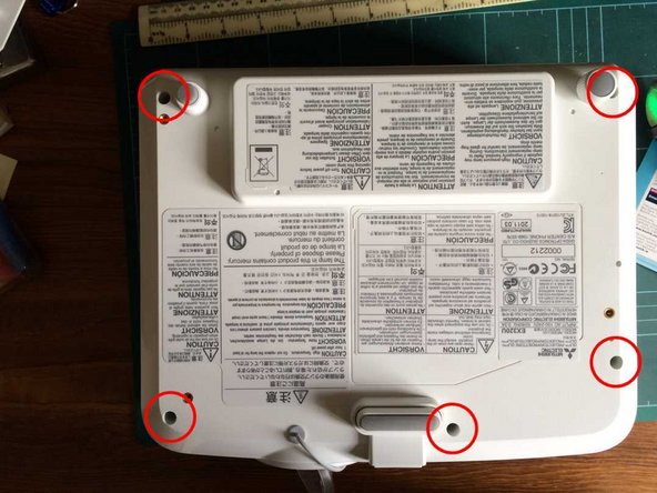
Turn the projector over and remove 5 screws from the bottom. These are quite deeply recessed and you will need a screwdriver at least 6cm long.
-
Turn the projector the right way up again and work around the top cover with a spudger to release it from its clips. Lift the top cover off.
-
-
-
-
Remove 3 screws from the back of the projector.
-
Remove 8 binding posts from the D-type connectors, using a 5mm socket.
-
The plastic back panel can now be lifted out.
-
Lift off the metal shield, gently releasing the clips on the sides and the front, and easing it over the sockets at the back.
-
-
-
Gently pull the ribbon cable by the optical assembly out of its socket.
-
Disconnect 7 other cables.
-
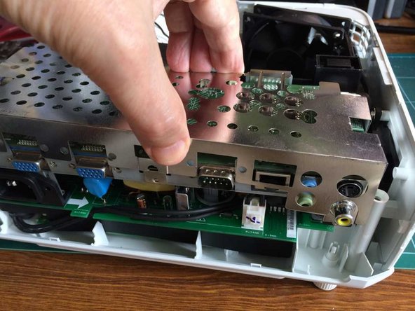
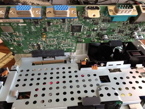
You can now lift off and put aside the main logic board by easing it upwards from the front. When you get it off you will see that it was retained by 2 connectors: an edge connector on the optical assembly and a pin block to the right connecting it to the power supply board below.
-
-
-
Remove 3 self-tapping screws which fasten the metal plate to plastic posts below. You will need a long screwdriver and it will help greatly if it's magnetic. The rear screw on the right also retains an earthing lead.
-
Remove a machine screw and its earthing lead.
-
Lift off the metal plate.
-
-
-
Remove 3 screws retaining the optical assembly. Note that only one of the two screws on the right should be removed.
-
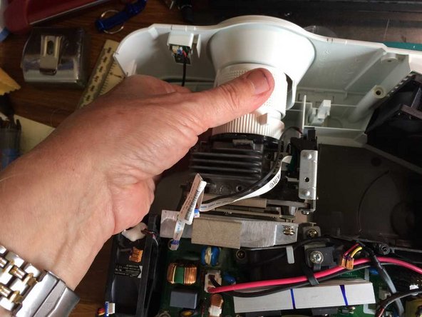
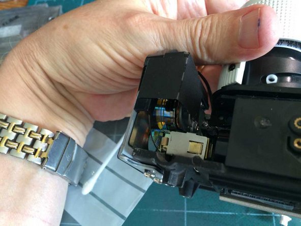
Gently lift out the optical assembly, disengaging the lens from the front panel.
-
-
-
Remove 4 screws and lift off the heat sink and DLP chip.
-
Inspect the DLP for any dust. You can wipe it gently with a cotton wool bud moistened with isopropyl alcohol.
-
-
-
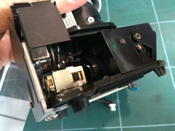
Follow the light path and inspect carefully for dust or contamination. These pictures show the optical assembly upside down.
-
Light enters from the lamp on the right, facing the screen (on the left in this picture since it's upside down).
-
The light then passes through the colour wheel ...
-
... and into the collimator.
-
-
-
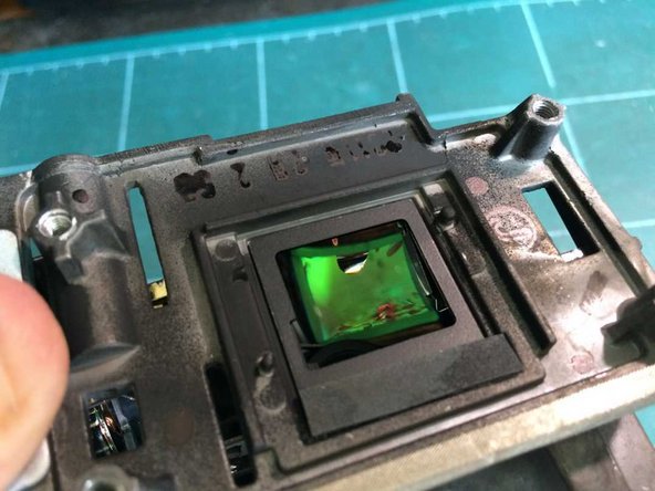
The light enters the imaging chamber on the right (the left in the picture, as again, it's upside down).
-
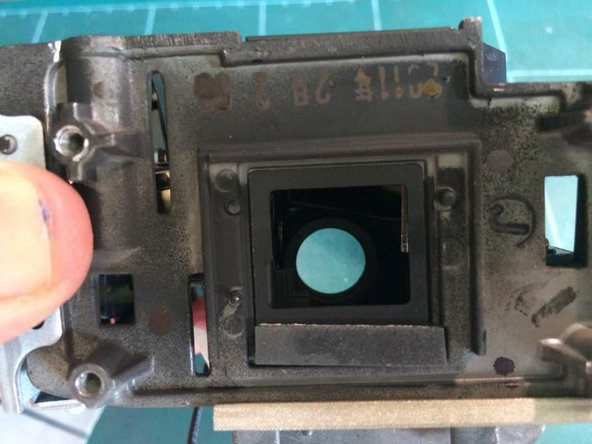
The light is reflected off a mirror in the floor of the chamber, focussing it onto the DLP chip, which is located in the aperture we're looking through.
-
From the DLP chip, the light is reflected through the projection lens and hence on to the screen.
-


To reassemble your device, follow these instructions in reverse order.
To reassemble your device, follow these instructions in reverse order.
Annuleren: ik heb deze handleiding niet afgemaakt.
3 andere personen hebben deze handleiding voltooid.

Team

3 opmerkingen
muy buenas tengo el proyector es200u muy similar a este…
tengo un problema, lo he desarmado y tengo una pieza que no se donde va…. ¿me puedes ayudar? mi correo es discobolero@gmail.com
Por favor, publique una foto de la pieza y tal vez podamos ayudarlo.