Deze versie kan foutieve bewerkingen bevatten. Schakel over naar de recentste gecontroleerde momentopname.
Wat je nodig hebt
-
Deze stap is niet vertaald. Help het te vertalen
-
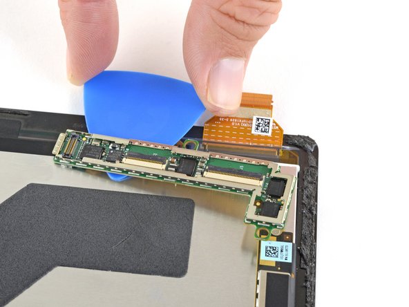
Use a spudger to flip up the small locking flaps on the display cable ZIF connectors.
-
-
Deze stap is niet vertaald. Help het te vertalen
-
Use tweezers to slide the display cables straight out of their sockets on the display board.
-
-
Deze stap is niet vertaald. Help het te vertalen
-
Slide an opening pick under the display board to separate the adhesive holding it onto the back of the screen.
-
-
Deze stap is niet vertaald. Help het te vertalen
-
Remove the display board.
-
To ensure correct positioning, plug in both display connectors before adhering the board to the display.
-
-
-
Deze stap is niet vertaald. Help het te vertalen
-
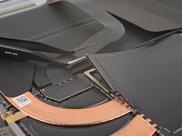
Insert one point of a pair of pointed tweezers into a gap in the corner of the EMI shield covering the heat sink.
-
Use the tweezers to pry the EMI shield away from the motherboard as much as you can without bending it. Do not remove it yet.
-
-
Deze stap is niet vertaald. Help het te vertalen
-
Repeat the last step for each corner of the EMI shield covering the heat sink.
-
-
Deze stap is niet vertaald. Help het te vertalen
-
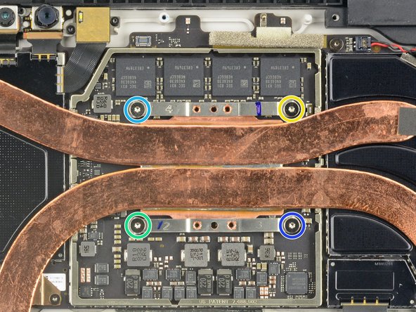
Remove the ten Torx screws securing the heat sink:
-
Five 2.6 mm-long T3 screws
-
Four 3.3 mm-long T5 screws
-
Screw 1
-
Screw 2
-
Screw 3
-
Screw 4
-
-
Deze stap is niet vertaald. Help het te vertalen
-
Use the flat end of a spudger to gently pry the heat sink straight up and off of the CPU.
-
-
Deze stap is niet vertaald. Help het te vertalen
-
Remove the Torx T5 x 6mm screw connecting the black tie bar to the power button/volume control/speaker assembly.
-
-
Deze stap is niet vertaald. Help het te vertalen
-
Remove the remaining three Torx T5 x 4.5mm screws holding down the camera tie bar.
-
-
Deze stap is niet vertaald. Help het te vertalen
-
Disconnect the small ribbon cable connecting the camera tie bar to the motherboard by pulling up with tweezers.
-


Annuleren: ik heb deze handleiding niet afgemaakt.
Één andere persoon heeft deze handleiding voltooid.
Team

Cal Poly, Team S15-G3, Livingston Fall 2017 Lid van Cal Poly, Team S15-G3, Livingston Fall 2017
CPSU-LIVINGSTON-F17S15G3
3 Leden
17 handleidingen geschreven
2 opmerkingen
Do you really need to remove the heat sink shield and the heat sink to disconnect the tie bar small ribbon cable ?