Deze versie kan foutieve bewerkingen bevatten. Schakel over naar de recentste gecontroleerde momentopname.
Wat je nodig hebt
-
-
Verwijder de volgende tien schroeven die de onderste behuizing aan de bovenste behuizing bevestigen:
-
Drie 13.5 mm (14.1 mm) lange Phillips schroeven.
-
Zeven 3 mm lange Phillips schroeven.
-
-
-
Gebruik de platte kant van een spudger om de batterijaansluiting uit het contact op het logic board omhoog te duwen.
-
-
Deze stap is niet vertaald. Help het te vertalen
-
Remove the three 3.4 mm T6 Torx screws securing the left fan to the logic board.
-
-
Deze stap is niet vertaald. Help het te vertalen
-
Use the flat end of a spudger to disconnect the left fan connector from the logic board.
-
-
Deze stap is niet vertaald. Help het te vertalen
-
Use the flat end of a spudger to lift the right fan connector out of its socket on the logic board.
-
-
Deze stap is niet vertaald. Help het te vertalen
-
Remove the three 3.4 mm (3.1 mm) T6 Torx screws securing the right fan to the logic board.
-
Lift the right fan out of its opening in the logic board.
-
-
Deze stap is niet vertaald. Help het te vertalen
-
Pull the camera cable out of its socket on the logic board.
-
-
Deze stap is niet vertaald. Help het te vertalen
-
Use the flat end of a spudger to pry the AirPort/Bluetooth connector up from its socket on the logic board.
-
-
Deze stap is niet vertaald. Help het te vertalen
-
Use the flat end of a spudger to lift the optical drive connector out of its socket on the logic board.
-
-
Deze stap is niet vertaald. Help het te vertalen
-
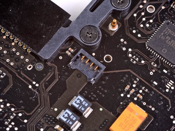
Disconnect the hard drive/IR sensor cable from its socket on the logic board by lifting up from beneath its connector.
-
-
Deze stap is niet vertaald. Help het te vertalen
-
Use the flat end of a spudger to lift the subwoofer/right speaker connector out of its socket on the logic board.
-
-
Deze stap is niet vertaald. Help het te vertalen
-
Remove the two 1.5 mm ( 1.2 mm ) Phillips screws securing the keyboard/trackpad cable cover to the logic board.
-
Lift the cover off the logic board and set it aside.
-
-
Deze stap is niet vertaald. Help het te vertalen
-
Use the flat end of a spudger to pry the trackpad connector up and out of its socket on the logic board.
-
-
-
Deze stap is niet vertaald. Help het te vertalen
-
Use your fingernail to flip up the retaining flap on the keyboard ribbon cable ZIF socket.
-
Use the tip of a spudger to pull the keyboard ribbon cable out of its socket.
-
-
Deze stap is niet vertaald. Help het te vertalen
-
Use the flat end of a spudger to lift the battery indicator connector up and out of its socket on the logic board.
-
-
Deze stap is niet vertaald. Help het te vertalen
-
Grab the plastic pull tab secured to the display data cable lock and rotate it toward the DC-In side of the computer.
-
Pull the display data cable straight out of its socket on the logic board.
-
-
Deze stap is niet vertaald. Help het te vertalen
-
Use the tip of a spudger to flip up the retaining flap on the keyboard backlight ribbon cable ZIF socket.
-
Pull the keyboard backlight ribbon cable out of its socket.
-
-
Deze stap is niet vertaald. Help het te vertalen
-
Remove the following nine screws:
-
Seven 3.4 mm ( 3.1 mm) T6 Torx screws on the logic board
-
Two 8 mm T6 Torx screws on the DC-In board
-
-
Deze stap is niet vertaald. Help het te vertalen
-
Carefully lift the logic board assembly from its left side and work it out of the upper case, minding the optical drive cable and the I/O ports that may get caught during removal.
-
If necessary, use the flat end of a spudger to separate the microphone from the upper case.
-
Pull the I/O port side of the logic board away from the side of the upper case and remove the logic board assembly.
-
-
Deze stap is niet vertaald. Help het te vertalen
-
Remove the two 7.5 mm ( 7.2 mm )Tri-point screws securing the battery to the upper case.
-
-
Deze stap is niet vertaald. Help het te vertalen
-
Carefully peel the battery warning label off the upper case between the battery and the optical drive to reveal an additional Tri-point screw.
-
Remove the last 7.5 mm ( 7.2 mm ) Tri-point screw securing the battery to the upper case.
-
-
Deze stap is niet vertaald. Help het te vertalen
-
Use the attached plastic pull tab to remove the battery from the upper case.
-
-
Deze stap is niet vertaald. Help het te vertalen
-
Remove the two Phillips screws securing the hard drive bracket to the upper case.
-
Remove the hard drive bracket from the upper case.
-
-
Deze stap is niet vertaald. Help het te vertalen
-
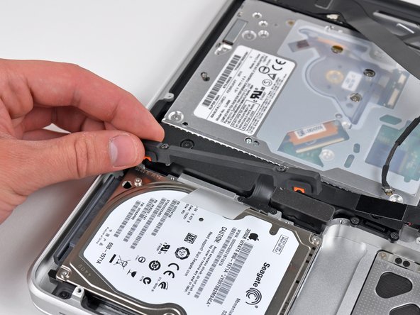
Using its attached pull tab, lift the hard drive out of the upper case.
-
-
Deze stap is niet vertaald. Help het te vertalen
-
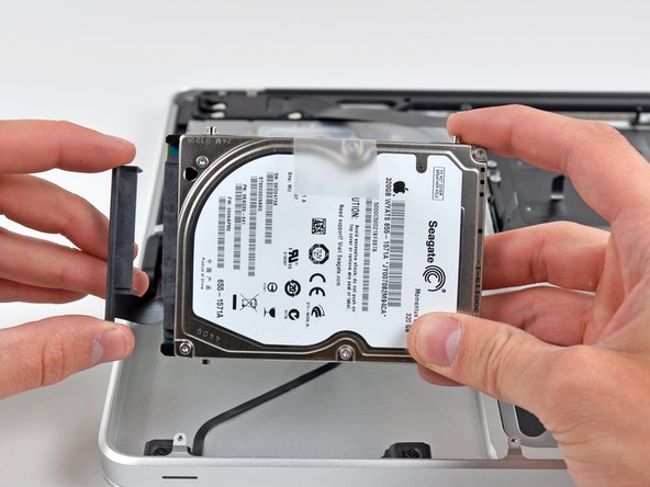
Pull the hard drive connector out of its socket on the hard drive.
-
Remove the hard drive and set it aside.
-
-
Deze stap is niet vertaald. Help het te vertalen
-
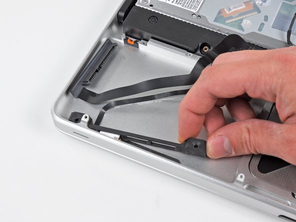
Remove the following four screws securing the hard drive/IR sensor cable to the upper case:
-
Two 2.5 mm ( 2.9 mm ) Phillips screws
-
Two 10 mm ( 9.6 mm ) Phillips screws
-
-
Deze stap is niet vertaald. Help het te vertalen
-
Carefully peel the IR sensor cable off the adhesive securing it to the upper case.
-
Pull the hard drive bracket/IR sensor housing away from the side of the upper case.
-
Remove the hard drive/IR sensor cable from the upper case.
-
-
Deze stap is niet vertaald. Help het te vertalen
-
Use the tip of a spudger to pry the four antenna connectors up from their sockets on the AirPort/Bluetooth board.
-
-
Deze stap is niet vertaald. Help het te vertalen
-
De-route all four antenna cables from their channels in the AirPort/Bluetooth housing.
-
De-route the camera cable from its channel in the AirPort/Bluetooth housing.
-
-
Deze stap is niet vertaald. Help het te vertalen
-
Remove the following two screws:
-
One 8.6 mm ( 8.4 mm ) Phillips screw
-
One 3.9 mm Phillips screw
-
Remove the AirPort/Bluetooth assembly from the upper case, minding any cables that may get caught.
-
-
Deze stap is niet vertaald. Help het te vertalen
-
Remove the three 3.5 mm ( 3.3 mm ) T6 Torx screws securing the optical drive to the upper case.
-
Lift the optical drive near its connector and pull it away from the upper case to remove it from the computer.
-
-
Deze stap is niet vertaald. Help het te vertalen
-
Remove the following six screws securing the subwoofer and right speaker to the upper case:
-
Two 3.2 mm ( 3.0 mm ) Phillips screws.
-
Two 12.3 mm Phillips screws.
-
One 2.5 mm Phillips screw.
-
One 8.3 mm ( 8.1 mm ) Phillips screw.
-
Lift the subwoofer and right speaker assembly out of the upper case.
-
-
Deze stap is niet vertaald. Help het te vertalen
-
Remove the 8.6 mm Phillips screw securing the antenna/camera cable retainer to the top left portion of the upper case.
-
Remove the antenna/camera cable retainer from the upper case.
-
-
Deze stap is niet vertaald. Help het te vertalen
-
Remove the 8.6 mm ( 7.0 mm ) Phillips screw securing the display data cable retainer to the top right portion of the upper case.
-
Remove the display data cable retainer from the upper case.
-
-
Deze stap is niet vertaald. Help het te vertalen
-
Remove two of the three 6 mm T6 Torx screws securing the right side of the display to the upper case.
-
-
Deze stap is niet vertaald. Help het te vertalen
-
Remove two of the three 6 mm T6 Torx screws securing the left side of the display to the upper case.
-
-
Deze stap is niet vertaald. Help het te vertalen
-
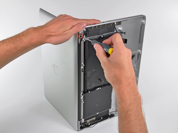
Open your MacBook Pro so the display is perpendicular to the upper case.
-
Place your opened MacBook Pro on a table as pictured.
-
While holding the display and upper case together with your left hand, remove the remaining T6 Torx screw from the upper display bracket.
-
-
Deze stap is niet vertaald. Help het te vertalen
-
Remove the last remaining T6 Torx screw securing the display to the upper case.
-
-
Deze stap is niet vertaald. Help het te vertalen
-
Grab the upper case with your right hand and rotate it slightly toward the top of the display so the upper display bracket clears the edge of the upper case.
-
Rotate the display slightly away from the upper case.
-
Lift the display up and away from the upper case, minding any brackets or cables that may get caught.
-
-
Deze stap is niet vertaald. Help het te vertalen
-
If your replacement includes the battery level indicator, stop here.
-
Remove three 2.0 mm Phillips #00 screws securing the battery level indicator to the upper case.
-
-
Deze stap is niet vertaald. Help het te vertalen
-
Use the tip of a spudger to gently pry up the edge of the metal shield covering the battery level indicator cable.
-


Annuleren: ik heb deze handleiding niet afgemaakt.
34 andere personen hebben deze handleiding voltooid.
